-
Contents
-
Table of Contents
-
Troubleshooting
-
Bookmarks
Quick Links
Doc. No. 1SDH000760R0002 — L8884
Automatic transfer switch ATS022
Installation and operating instructions
Related Manuals for ABB ATS022
Summary of Contents for ABB ATS022
-
Page 1
Doc. No. 1SDH000760R0002 — L8884 Automatic transfer switch ATS022 Installation and operating instructions… -
Page 3: Table Of Contents
Introduction ……………………6 Product overview ………………………6 Application scenarios ……………………7 Applications of device ATS022 ………………8 Switching Main Line – Emergency generator (2CBs) …………..9 Non priority loads control (NPL) ………………..10 Control of two independent power supply lines separated by Tie (3CBs Bus Tie) …..14 Automatic switching without inverse procedure ……………..15…
-
Page 4: Safety Notes
If there are doubts about safe use, the unit must be put out of service. The automatic transfer switch ATS022 must be prevented from operating the circuit breakers before: • accessing the circuit breakers • performing maintenance on circuit breakers or any electrical circuits powered by them •…
-
Page 5: Explanation Of Abbreviations And Terms
2. Explanation of abbreviations and terms Installation and operating instructions, ATS022 2. Explanation of abbreviations and terms 2.1. General information ATS: Automatic Transfer Switch; automatic switching device. ATS022: ATS of the ATS02x series, version with display and Modbus communication. Circuit Breaker; low voltage automatic Circuit Breaker.
-
Page 6: Introduction
• utilisation in single-phase systems with Un 57,5…109VAC A 24VDC ….110VDC auxiliary safety power supply can be used (-10%, +15%). ATS022 can be used in systems with rated frequency 50Hz, 60Hz, 400Hz, 16 2/3 Hz that can be set from the menu.
-
Page 7: Application Scenarios
• control of two independent power supply lines separated by Bus Tie (3CBs Bus Tie) The ATS022 also makes it possible to select which of the lines is the main one and which one is secondary, also with the system running.
-
Page 8: Applications Of Device Ats022
Installation and operating instructions, ATS022 Applications of device ATS022 4. Applications of device ATS022 The ATS022 device controls all the switching sequences by applying the time delays that can be set: Time delays Description Value Opening delay of main line CB after detection of a fault in the mains (Generator is not in use).
-
Page 9: Switching Main Line — Emergency Generator (2Cbs)
4.2 Switching Main Line – Emergency generator (2CBs) Description In case of main line failure ATS022 automatically starts up an emergency generator and, as soon as power on the generator side is available, ATS022 starts the automatic switching procedure. Figure 4.3: 2CBs application layout –…
-
Page 10: Non Priority Loads Control (Npl)
4.3 Non priority loads control (NPL) Description In case of main line failure the ATS022 starts the switching procedure and controls the non priority loads by opening closing circuit breaker CB3. ATS022 acquires the CB3 open/close status from the dedicated input DI11 and commands the opening and closing by activating output DO11.
-
Page 11
Installation and operating instructions, ATS022 Applications of device ATS022 configuration requires configuration with 2 lines or with a line and an emergency generator. Figure 4.5: Application layout 3CBs NPL BUSTIE Figure 4.6: Application layout 3CBs NPL 1SDH000760R0002… -
Page 12
Installation and operating instructions, ATS022 Applications of device ATS022 Time diagrams Line 1 ok CB1 CLOSED Gen start Line 2 ok CB2 CLOSED CB3 CLOSED TGOFF Figure 4.7: Application time diagram 3CBs NPL BUS TIE — generator in use Line 1 ok… -
Page 13
Installation and operating instructions, ATS022 Applications of device ATS022 Line 1 ok CB1 CLOSED Gen start Line 2 ok CB2 CLOSED CB3 CLOSED TGOFF Figure 4.9: Application time diagram 3CBs NPL- generator in use Line 1 ok CB1 CLOSED Line 2 ok… -
Page 14: Control Of Two Independent Power Supply Lines Separated By Tie (3Cbs Bus Tie)
Lines LN1 and LN2 supply two different sections of the plant separated by a bus tie circuit breaker CB3, normally open. In case of failure of one of the two supply lines, ATS022 closes CB3; the available line thus powers both the sections downline. When the line is restored ATS022 restores the normal plant conditions by opening CB3.
-
Page 15: Automatic Switching Without Inverse Procedure
CB1 is opened. ATTENTION If ATS022 is not powered by the auxiliary supply and by any of the two lines the device waits for at least one of the two lines (5) to return before proceeding with the switching procedure (6).
-
Page 16: Line Priority Selection
Applications of device ATS022 Line Priority Selection Description ATS022 allows selection of the main line by means of the menu on the display. The following selections are possible: — main line: Line LN1 — main line: Line LN2 (selection possible only if generator is not in use)
-
Page 17: Using The Automatic Transfer Switch
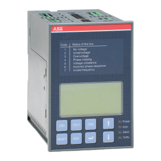
Voltage unbalance Incorrect phase sequence Invalid frequency R E S E T Figure 5.1: Description of ATS022 front panel interface Ref. Description CB1: pushbutton for opening/closing circuit breaker CB1 CB2: pushbutton for opening/closing circuit breaker CB2 CB3: CB3 opening/closure procedure graphic indication (combination of UP-DOWN keys for at…
-
Page 18: Led Indicators
1 minute). When the Powersave period ends, the LED switches off and the device awaits a line voltage. The moment the normal or the emergency line is restored, with ATS022 in automatic, the unit analyses the conditions of the lines monitored and the status of the circuit breakers and proceeds with the switching operation in accordance with the situation concerned.
-
Page 19: Keypad Keys
TEST key Press the TEST key to set the test modes of the direct and inverse switching sequences. ATS022 must be in the manual position. To exit TEST mode press RESET. Enter key Used for confirming the action or entry to the menu.
-
Page 20: Setting The Operating Modes
To select the Automatic operating mode of unit ATS022: a. Make sure the Power LED is On, see Figure 5.3/1 b. Press RESET once, see Figure 5.3/2. If the Auto LED is ON, the automatic transfer switch ATS022 is in Automatic mode, see Figure 5.3/3 c.
-
Page 21: Graphic Display
Installation and operating instructions, ATS022 Using the automatic transfer switch 5.5 Graphic Display LN1: 1 TBS.. LN2: 1 Figure 5.4: Description of ATS022 display Ref. Description LN1: line 1 LN2: line 2 CB1 status graphic indicator CB2 status graphic indicator…
-
Page 22: Ln1 And Ln2 Lines Status Indication
3P + N configuration. Table 5.3: Description of line status codes ATS022 5.5.2 Browsing through the Menu Press Enter to access the main Menu. Three different levels of configuration of the unit can be accessed from the main menu: Figure 5.5:…
-
Page 23
240V/138V — 277V/160V — 347V/200V — 400V/230 V 380V/220V — 400V/230V — 415V/240V — 440V/254V — 480V/277V Table 5.4: Description of parameters of lines ATS022 — Type of application Type of application Value Factory settings 2CBs / 3CBs NPL opening only / 3CBs NPL… -
Page 24
Table 5.9: Description of Modbus parameters ATS022 — Language and backlit display Function Value Factory settings Backlighting duration Always On, 0…59s, step 1s, 1,2,3…30min, step 1min Always On English/Italian/German/French/Spanish/Finnish/ Language English Russian/Chinese Table 5.10: Description of language and backlighting ATS022 1SDH000760R0002… -
Page 25
The log is cleared by selecting Clear Log and pressing Enter. Diagnostics Measured Values Alarm Log SW: 1A SN: 12345678 Figure 5.5: Description of diagnostics menu ATS022 Figure 5.6: diagnostics – values measured page ATS022 Figure 5.7: diagnostics – Alarms Log page ATS022 1SDH000760R0002… -
Page 26: Using Pushbuttons In Manual Mode
Installation and operating instructions, ATS022 Using the automatic transfer switch 5.6 Using pushbuttons in manual mode Opening/Closing circuit breakers CB1, CB2 In manual mode the circuit breakers can be controlled by means of pushbuttons CB1 and CB2. In case of a fault, the alarms are activated by the same methods as those for the automatic switching sequence.
-
Page 27: Test Modes
This test mode makes it possible to test only the generator start and stop with the plant running without opreating the circuit breakers on the line in any manner whatsoever, only if the ATS022 is set with the generator in use, otherwise the Gen Set Test is not performed.
-
Page 28: Modbus Communication
ATS022 that are remotly available. In the ABB library it is also possible to download the software ABB EKIP connect 2 that enables a rapid and easy remote management of the measures , parameters, and the commands of ATS022.
-
Page 29: Input And Output Signals
— Time TL: time that the fault is present on both lines after which the contact is activated. — Function DO7: the parameter available on ATS022 is a number in decimal format that, if converted into binary, allows 6 bits to be managed corresponding to the types of alarms (bit set to 0= alarm deactivated;…
-
Page 30
The Unbalance alarm also includes cases of undervoltage or overvoltage (for example, the drop of one phase in a 3P or 3P + N system). In the absence of voltages, ATS022 cannot calculate the angle between the various phases and therefore it considers this condition as: Incorrect phase sequence. -
Page 31: Input Signals
DI3 Switching Logic Activation/Deactivation Input DI3 is used for enabling/disabling the switching logic. The function may be used for integrating generic alarms coming from the plant the presence of which leads to disabling of ATS022 automatic switching logic. • DI3 open: logic disabled •…
-
Page 32
When the circuit breaker is inserted: • the position indication contact closes • the switching logic is re-enabled • Alarm LED switches Off • ATS022 operates in manual mode • contact DO10 is closed • Alarm contact DO6 is opened • contact DO12 is opened •… -
Page 33
Open =gen start; Closed = gen stop Closed =gen start; Open = gen stop The DI10 contact programmed as a generator starting override is active with ATS022 configured with priority line LN1 and with backswitching. If one of these conditions does not exist, the option is not available or, if activated previously, will be automatically DISABLED. -
Page 34
• LN1 present: DI10 determines the activation and deactivation of the generator. • Switching in progress or line LN2 present: DI10 is ignored by ATS022. When changing over from automatic to manual, DI10 is handled differently depending on the initial state of the command to the generator: •… -
Page 35
Installation and operating instructions, ATS022 Input and output signals Linea 2 ATS022 Line 2 Linea 1 Linea 2 Line 1 Ligne 2 Linea 1 Leitung 2 Ligne 1 Leitung 1 Uscita per controllo Gen Start/Stop Output to control Gen Start/Stop… -
Page 36
Installation and operating instructions, ATS022 Input and output signals Connectors Description DI/DO Type X11:1 Normal Line LN1: L1 X11:2 Normal Line LN1: L2 X11:3 Normal Line LN1: L3 X11:4 Normal Line LN1: N X12:1 Emergency Line LN2: L1 X12:2 Emergency Line LN2: L2… -
Page 37
CB2 trip input 0=CB trip; I=no CB trip X32:8 CB1 trip input 0=CB trip; I=no CB trip X32.9 X51:1 Modbus DATA B X51:2 Modbus DATA A X52:3 Modbus GND Earth connection Table 6.2: Description of function and type connector ATS022 1SDH000760R0002… -
Page 38: Technical Data
In case of rated frequency 16 2/3 Hz, an auxiliary safety power supply must be used. If the rated voltage is greater than 100 VAC external transformers must be used. If the ATS022 is used in environments with extremely low temperatures (less than — 10°C) it is advisable to use a safety auxiliary power supply to avoid display problems of the graphic display.
-
Page 39: Installation Of Device Ats022
Installation of device ATS022 8. Installation of device ATS022 The automatic transfer switch ATS022 can be mounted on the front of the panel door or on DIN rail. 8.1. Door-mounted Automatic Transfer Switch ATS022 The Automatic Transfer Switch ATS022 can be door-mounted as shown in Figure 8.1.
-
Page 40: Din Rail-Mounted Automatic Transfer Switch Ats022
Installation and operating instructions, ATS022 Installation of device ATS022 8.2. DIN rail-mounted Automatic Transfer Switch ATS022 The automatic transfer switch ATS022 can be mounted on a 35mm DIN rail as shown in Figure 8.2. 35mm EN 50022 Togliere Figure 8.2:…
-
Page 41: Regulatory Standards
Regulatory standards Installation and operating instructions, ATS022 9. Regulatory standards ATS022 conforms to the following regulatory standards: • European Directive 73/23 “LVD – Low Voltage Directive” • EN 50178 electronic equipment for use in power Installations • EN-IEC 62103 electronic equipment for use in power Installations •…
-
Page 42: Troubleshooting
10. Troubleshooting Installation and operating instructions, ATS022 10. Troubleshooting The alarms are shown by means of a message on the ATS022 display. The Alarm messages are shown in the Table below: Table 10.1: Alarms ATS022 Alarm Fault Action circuit breaker CB1 on normal line…
-
Page 43
Due to possible development of Standards as well as of materials, the characteristics and dimensions specified in this Installation and operating instructions may be considered as binding only after confirmation by ABB SACE Division. © Copyright 2011-2016 ABB. All rights reserved.
(Ocr-Read Summary of Contents of some pages of the ABB ATS022 Document (Main Content), UPD: 18 May 2023)
-
9, ABB ATS022 9 1SDH000760R0002, L4106 Installation and operating instructions, ATS022 2. Product overview The device has an external auxiliary power supply possibility for guarantying an uninterrupted power supply for the protection devices in the case where they are not powered through the control circuit. From the display, one can choose whether the N-line is connected or not. Figure 2.6 The circuit diagram, when N-line is not connected. Figure 2.5 An external 24…110 Vdc aux…
-
28, Installation and operating instructions, ATS022 1SDH000760R0002, L4106 28 8.2.2 LEDs Figure 8.3 LEDs on ATS022 Alarm A red Alarm LED signals an active alarm with continuous red signal (Logic disabled, CBs commands failure, CBs trips, CBs withdrawn, Gen. alarm input DI8, DI3 activated). Auto A green Auto LED signals the automatic or the manual mode. When the automatic transfer switch ATS022 is in automatic mode, the Auto LED is ON. When the device is in manua…
-
11, 11 1SDH000760R0002, L4106 Installation and operating instructions, ATS022 3.2.2 CB Withdrawn In the case of withdrawable circuit breakers, the auxiliary contacts for the CB inserted are connected to these inputs (withdrawn=open contact). In the case of a withdrawn circuit breaker, the transfer switch logic is disabled (DO6 activated, Alarm LED is ON) and the unit goes in the Manual Mode (DO10 activated, Auto LED is…
-
35, ABB ATS022 35 1SDH000760R0002, L4106 Installation and operating instructions, ATS022 Modbus Communication protocol. User can set Address, Baud Rate, Stop Bits and Parity for the Modbus. Address means the Modbus address of the device. The address can be chosen between 1 … 247. The Baud Rate can be 9600 –19200 – 38400 kbps. Stop bit can be set 0 or 1 and the parity can be set even, odd or none. Factory settings are Modbus address 1, Modbus Baud Rate 9600, Modbus …
-
37, 37 1SDH000760R0002, L4106 Installation and operating instructions, ATS022 8. Using automatic transfer switch ATS022 Figure 8.25 Alarm Log: 20 latest alarms, Clear Log will empty the log 8.2.4 Communication via Modbus An RS485 link is used to connect ATS022 with a PC or a PLC over a distance of 500 meters using Modbus protocol: RS485 2 or 3 wires half duplex Protocol Modbus in RTU mode Speed 2400, 4800, 1920…
-
16, Installation and operating instructions, ATS022 1SDH000760R0002, L4106 16 3. Description The switching sequence will be the following: An anomaly on the normal line occurs Delay time TS Start command to the generator Emergency line OK Opening of the protection device on the normal line Delay time TCE Closing of the protection device on the emergency line Meanwhile the back-switching sequence will be: Normal line OK Delay time TBS Opening of the protection de…
-
44, Producted by: KATANN Document Factory Oy, Vaasa Finland L.V. Breakers Via Baioni, 35 24123 Bergamo, Italy Telephone +39 035.395.111 Telefax +39 035.395.306-433 www.abb.com ABB SACE S.p.A An ABB Group company The technical data and dimensions are valid at the time of printing. We reserve the right to subsequent alterations.
… -
4, Installation and operating instructions, ATS022 1SDH000760R0002, L4106 4 1. Introduction Hazardous voltage: warns about a situation where a hazardous voltage may cause physical injury to a person or damage to equipment. General warning: warns about a situation where something other than electrical equipment may cause physical injury to a person or damage to equipment. Caution: provides important information or warns about a situation …
-
31, 31 1SDH000760R0002, L4106 Installation and operating instructions, ATS022 Rated Operational Voltage U e Rated Operational Voltage U e is the rated voltage of the system. Value is announced as main voltage/ phase voltage, Volts. Factory setting is 400/230 V. 8. Using automatic transfer switch ATS022 3 phases without N Cancel Ok Edit Number of Phases KA00383 Figure 8.8 Rated Operational Voltage U e , factory setting is 400/230 V Rated Frequency Rated Frequ…
-
34, Installation and operating instructions, ATS022 1SDH000760R0002, L4106 34 Frequency Thresholds User can set frequency thresholds both minimum and maximum values. Factory settings are min -1% and max 1%. KA00470 Delay Times Delay TS 1/5 Delay TCE Delay TBS Delay Times Delay TBS Delay TCN Delay TGOFF 5/5 KA00471 0 s Delay TS KA00472 Cancel Ok Edit 3 s Cancel Ok Edit Delay TCE KA00473 0 s Cancel Ok Edit Delay TBS KA00474 3 s Cancel Ok Edit Delay TCN KA00475 5 s C…
-
29, 29 1SDH000760R0002, L4106 Installation and operating instructions, ATS022 8. Using automatic transfer switch ATS022 LN1 LN2 KA00373 0,0 0,0 LN1: 1 V Hz LN2: 1 0,0 0,0 V Hz LN1 LN2 KA00372 230 50,0 LN1: 1 V Hz LN2: 1 0,0 0,0 V Hz 8.2.3 Display The display is a graphic display with following menu pages: 8.2.3.1 Default page Default page shows the status of the protection devices and the status of two monitored lines and …
-
17, 17 1SDH000760R0002, L4106 Installation and operating instructions, ATS022 4. Operating Before using of the automatic transfer switch ATS022, read carefully chapter 1 “Safety notes” in order to avoid malfunctions or dangerous operating conditions. 4.1 Automatic transfer switch ATS022 in Manual Mode Selecting the automatic transfer switch ATS022 to the Manual Mode: a. Make sure that power LED is ON, see the Figure 4.1/j. b. If Auto LED is OFF /…
-
20, Installation and operating instructions, ATS022 1SDH000760R0002, L4106 20 4. Operating 4.3 TEST sequence When pushing the TEST key, the automatic transfer switch (ATS022) enters the test sequence in which it is possible to simulate switching and back-switching sequences step-by-step, by pressing the TEST key. ATS022 must be in MANUAL mode before entering the test sequence. Exiting from test sequ…
-
22, Installation and operating instructions, ATS022 1SDH000760R0002, L4106 22 5. Installation KA00500 35mm EN 50022 3 2 1 Remove KA00484 1 2 3 5.2 Automatic transfer switch ATS022, DIN-rail mounting The automatic transfer switch ATS022 can be mounted on the 35 mm DIN-rail, see the Figure 5.2. Door drilling, if needed, according to Figure 5.2. Figure 5.2 Automatic transfer switch ATS022, DIN-rail mounting 174 9,5 114 115 97 145 5 Ø 19,5 KA00377
… -
13, 13 1SDH000760R0002, L4106 Installation and operating instructions, ATS022 3. Description Figure 3.2 Two transformer oncoming lines In this case, the installation scenario is the following: ATS is connected to two power incoming lines. Both lines are the secondary section of a medium-low voltage transformer or in any case, there are two lines normally present. One of the two lines has more importance; it is normally used to supply the plant. The second line is an emergency lin…
-
21, ABB ATS022 21 1SDH000760R0002, L4106 Installation and operating instructions, ATS022 5. Installation 5. Installation Only an authorised electrician may perform the electrical installation and maintenance of automatic transfer switch. Do not attempt any installation or maintenance actions when an automatic transfer switch is connected to the electrical mains. Before starting work, make sure that the circuit breaker is de-energised. Figure 5.1 Automatic…
Contents
Contents
1.
Safety notes ……………………………………………………………………………………………………….. 4
2.
2.1.
General information ………………………………………………………………………………………………………..5
2.2.
Times ……………………………………………………………………………………………………………………………5
3.
Introduction ………………………………………………………………………………………………………… 6
3.1
Product overview ……………………………………………………………………………………………………………6
3.2
Application scenarios …………………………………………………………………………………………………….7
4.
Applications of device ATS022 …………………………………………………………………………….. 8
4.2
4.3
Non priority loads control (NPL) ……………………………………………………………………………………..10
4.4
4.5
4.6
Line Priority Selection …………………………………………………………………………………………………..16
5.
5.1
Interface………………………………………………………………………………………………………………………17
5.2
LED indicators ……………………………………………………………………………………………………………..18
5.3
Keypad keys ………………………………………………………………………………………………………………..19
5.4
Setting the operating modes ………………………………………………………………………………………….20
5.4.1
Manual mode ……………………………………………………………………………………………………………….20
5.4.2
Automatic mode …………………………………………………………………………………………………………..20
5.5
Graphic Display ……………………………………………………………………………………………………………21
5.5.1
5.5.2
Browsing through the Menu …………………………………………………………………………………………..22
5.6
5.7
Test Modes ………………………………………………………………………………………………………………….27
5.8
Modbus Communication ……………………………………………………………………………………………….28
5.8.1
Local / Remote Configuration ………………………………………………………………………………………..28
6.
Input and output signals ……………………………………………………………………………………. 29
6.1
Output signals (DO1…DO12) …………………………………………………………………………………………29
6.2
Input signals ……………………………………………………………………………………………………………….31
7.
Technical data …………………………………………………………………………………………………… 38
8.
Installation of device ATS022 …………………………………………………………………………….. 39
8.1.
8.2.
9.
Regulatory standards ………………………………………………………………………………………… 41
10.
Troubleshooting ………………………………………………………………………………………………… 42
1SDH000760R0002
Installation and operating instructions, ATS022
3
Table of Contents for ABB ATS022:
-
Installation and operating instructions, ATS022 1SDH000760R0002, L4106 32 8. Using automatic transfer switch ATS022 Protection Devices User can choose whether protection devices is CBs or CBs + Bus Tie. CBs is the default. Line 1 First Cancel Ok Edit Line Priority KA00393 LN1 LN2 KA00374 0,0 0,0 LN1: 1 V Hz LN2: 1 0,0 0,0 V Hz LN1 LN2 KA00375 0,0 0,0 LN1: 1 V Hz LN2: 1 0,0 0,0 V Hz Figure 8.11 Protection Devices, CBs is the default Figure 8.12 Protection Devices, status is shown as a graphic picture G
-
11 1SDH000760R0002, L4106 Installation and operating instructions, ATS022 3.2.2 CB Withdrawn In the case of withdrawable circuit breakers, the auxiliary contacts for the CB inserted are connected to these inputs (withdrawn=open contact). In the case of a withdrawn circuit breaker, the transfer switch logic is disabled (DO6 activated, Alarm LED is ON) and the unit goes in the Manual Mode (DO10 activated, Auto LED is OFF). When a CB is re-inserted, the logic is enabled (DO6 disactivated, Alarm LED is OFF) and the ATS022 is in the Manual Mode (DO10 activated
-
41 1SDH000760R0002, L4106 Installation and operating instructions, ATS022 Notes
-
Installation and operating instructions, ATS022 1SDH000760R0002, L4106 38 The confi guration of ATS022 can be done only by display and keypad, but the status information of the monitored lines and of the ATS022 can be monitored via Modbus. The following information is available: Table 8.6 Dialogue functions of ATS022 8. Using automatic transfer switch ATS022 Func. code Address Description Type Values 3 2000 Normal line status Uint16 0x0 = Voltage OK 0x1 = V
-
Installation and operating instructions, ATS022 1SDH000760R0002, L4106 4 1. Introduction Hazardous voltage: warns about a situation where a hazardous voltage may cause physical injury to a person or damage to equipment. General warning: warns about a situation where something other than electrical equipment may cause physical injury to a person or damage to equipment. Caution: provides important i
-
33 1SDH000760R0002, L4106 Installation and operating instructions, ATS022 8.2.3.4 Device confi guration In this sub-page you can set the threshold of all monitored parameters and the time delay, see the table 8.3. You can change the password in this subpage. The password consists of four numbers, and is chosen with the arrow and enter keys. For all other attributes you can select and change the value by using the UP, DOWN and ENTER keys. +15 % Cancel Ok Edit Volt Threshold Ma
-
23 1SDH000760R0002, L4106 Installation and operating instructions, ATS022 6. Connecting 6. Connecting Only an authorised electrician may perform the electrical installation and maintenance of automatic transfer switches. Do not attempt any installation or maintenance actions when an automatic transfer switch is connected to the electrical mains. Before starting work, make sure that the circuit breaker is de-energised. 6.1 Power circuit o
-
17 1SDH000760R0002, L4106 Installation and operating instructions, ATS022 4. Operating Before using of the automatic transfer switch ATS022, read carefully chapter 1 “Safety notes” in order to avoid malfunctions or dangerous operating conditions. 4.1 Automatic transfer switch ATS022 in Manual Mode Selecting the automatic transfer switch ATS022 to the Manual Mode: a. Make sure that power LED is ON, see the Figure 4.1/j. b. If Auto LED is OFF /k, the automatic transfer switch is in Ma
-
37 1SDH000760R0002, L4106 Installation and operating instructions, ATS022 8. Using automatic transfer switch ATS022 Figure 8.25 Alarm Log: 20 latest alarms, Clear Log will empty the log 8.2.4 Communication via Modbus An RS485 link is used to connect ATS022 with a PC or a PLC over a distance of 500 meters using Modbus protocol: RS485 2 or 3 wires half duplex Protocol Modbus in RTU mode Speed 2400, 4800, 19200, 38400 Bauds Galvanic insulation 4 kV (1 min 50 Hz) Table 8.4 ATS022 c
-
Installation and operating instructions, ATS022 1SDH000760R0002, L4106 26 Power circuit Value ATS022 Rated operational voltage U e 100 — 480 Vac ±20% Phase — neutral 57.7 — 277 Vac ±20% Rated frequency 50 – 60 Hz, 16 2/3 Hz, 400 Hz ±10% Rated impulse withstand voltage U imp 6 kV 1-phase system: Rated operational voltage U e Phase — neutral 57.7 — 240 Vac ±20% AUX voltage, if voltage 57.7 — 109 Vac 24Vdc – 110Vdc (-10 to +15%) Operating te
-
13 1SDH000760R0002, L4106 Installation and operating instructions, ATS022 3. Description Figure 3.2 Two transformer oncoming lines In this case, the installation scenario is the following: ATS is connected to two power incoming lines. Both lines are the secondary section of a medium-low voltage transformer or in any case, there are two lines normally present. One of the two lines has more importance; it is normally used to supply the plant. The second line is an emergency line; it is used in case of an emergency. In standard
-
Installation and operating instructions, ATS022 1SDH000760R0002, L4106 10 3. Description 3.1 ATS outputs 3.1.1 Opening/closing command to circuit breakers, DO1…DO4 The output relays command the circuit breakers to open and close its releases. The confi guration of the output relays has been designed to allow the command of any type of motor operator through a direct connectio
-
Installation and operating instructions, ATS022 1SDH000760R0002, L4106 14 Figure 3.4 Logic operation when opening command is OK Closing Command During the switching sequence ATS022 sends the closing command to the protection device on emergency line. If this is not effectively closed in fi ve seconds, the “Close 2 Failure” alarm is activated and the Alarm LED will be switched ON. This alarm will lock the switching logic and can only be reset by pushing RESET key. 3. Description Figure 3.5 Logic operation when closing command fails KA0
-
Installation and operating instructions, ATS022 1SDH000760R0002, L4106 22 5. Installation KA00500 35mm EN 50022 3 2 1 Remove KA00484 1 2 3 5.2 Automatic transfer switch ATS022, DIN-rail mounting The automatic transfer switch ATS022 can be mounted on the 35 mm DIN-rail, see the Figure 5.2. Door drilling, if needed, according to Figure 5.2. Figure 5.2 Automatic transfer switch ATS022, DIN-
-
3 1SDH000760R0002, L4106 Installation and operating instructions, ATS022Contents Contents 1. Introduction ……………………………………………………………………………………………………….. 4 1.1 Use of symbols ……………………………………………………………………………………………………………..4 1.2 Standards ……………………………………………………………………………………………………
Questions, Opinions and Exploitation Impressions:
You can ask a question, express your opinion or share our experience of ABB ATS022 device using right now.

-
Contents
-
Table of Contents
-
Troubleshooting
-
Bookmarks
Quick Links
Automatic transfer switch ATS022
Installation and operating instructions
1SDH000760R0002
Related Manuals for ABB ATS022
Summary of Contents for ABB ATS022
-
Page 1
Automatic transfer switch ATS022 Installation and operating instructions 1SDH000760R0002… -
Page 3: Table Of Contents
Installation ……………………21 Automatic transfer switch ATS022, door mounting …………..21 Automatic transfer switch ATS022, DIN-rail mounting ……………22 Connecting ……………………23 Power circuit of the automatic transfer switch ATS022 …………..23 Control circuit ……………………..23 6.2.1 Control circuit of the automatic transfer switch ATS022 …………24 Technical data …………………….
-
Page 4: Introduction
Installation and operating instructions, ATS022 1. Introduction 1. Introduction This manual describes the installation and the basic operation of the automatic transfer switch ATS022 used with circuit breakers. 1.1 Use of symbols Hazardous voltage: warns about a situation where a hazardous voltage may cause physical injury to a person or damage to equipment.
-
Page 5: Safety Notes
1.3 Safety notes If there are doubts about safety use, the unit must put out of service. The automatic transfer switch ATS022 must be prevented from operating the circuit breaker before accessing the circuit breakers performing maintenance on circuit breakers or any electrical circuits powered by them…
-
Page 6: Explanations Of Abbreviations And Terms
Switching delay, time after which ATS022 sends an opening command to the protection device on the normal line TCE: Close emergency delay, time after which ATS022 sends a closing command to the protection device on the emergency line TBS: Back switching delay, time after which ATS022 sends an opening command to the…
-
Page 7: Product Overview
Figure 2.1 Network line — GenSet line B. Network line a – Network line b In case of loss of the main’s network the ATS022 device manages the switching to a second line used as an emergency source. Figure 2.2…
-
Page 8: Functions Of Automatic Transfer Switch Ats022
The status of ATS022 can be monitored through the Modbus RTU connection. The ATS022 has a graphic display where the user is able to check the settings and get all the information about status of the ATS022.
-
Page 9
Installation and operating instructions, ATS022 2. Product overview The device has an external auxiliary power supply possibility for guarantying an uninterrupted power supply for the protection devices in the case where they are not powered through the control circuit. From the display, one can choose whether the N-line is connected or not. -
Page 10: Description
Installation and operating instructions, ATS022 3. Description 3. Description 3.1 ATS outputs 3.1.1 Opening/closing command to circuit breakers, DO1…DO4 The output relays command the circuit breakers to open and close its releases. The confi guration of the output relays has been designed to allow the command of any type of motor operator through a direct connection.
-
Page 11: Cb Withdrawn
A Gen-set alarm prevents switching to the emergency line. In the case of the power supply from the emergency line, when an alarm occurs, ATS022 keeps the line 2 with logic OFF; to enable the logic the alarm must be reset.
-
Page 12: Voltage Sensors Input
TBS = Back switching delay, 0…30 s Figure 3.1 Automatic Switching Sequences 3.3 Application scenarios The ATS022 can be used in different installation scenarios: Two transformer incoming lines One transformer incoming line and an emergency generator on the emergency line 1SDH000760R0002, L4106…
-
Page 13: Two Transformer Incoming Lines
If Line 1 (= the normal line) comes back, after the set time delay (TBS) the ATS022 sends an opening command to the protection device on the emergency line and the closing command to the protection device on the normal line is executed after a set time delay (TCN).
-
Page 14
Protection devices do not respond Opening Command During the switching sequence, the ATS022 sends the opening command to the protection device on the normal line. If this is not effectively opened in fi ve seconds, the “Open 1 Failure” alarm is activated and the Alarm LED will be switched ON. -
Page 15: Transformer On Normal Line And Generator On Emergency Line
Missing of both lines The missing of both lines is indicated by a blinking Power LED. In this case, the ATS022 will be in a power saving state. If both lines are missing more than one minute, the ATS022 will shut down.
-
Page 16: Special Scenarios
Two transformers and bus tie (Managing secondary loads): In this scenario, the ATS022 has to be able to control a third protection device used by the bus tie. ATS022 acquires the open/closed status of this device with digital input DI11 and by activating DO11 ATS022 is able to disconnect the secondary loads.
-
Page 17: Operating
4. Operating 4. Operating Before using of the automatic transfer switch ATS022, read carefully chapter 1 “Safety notes” in order to avoid malfunctions or dangerous operating conditions. Never open any covers on the product. There may be dangerous external control voltages inside the ATS022 automatic transfer switch even if the voltage is turned off.
-
Page 18
Installation and operating instructions, ATS022 4. Operating To select the operating line by the automatic transfer switch ATS022 in Manual Mode: a. Push the appropriate CB1 or CB2 key b. When pushing the CB1 key (see the Figure 4.2/k), the circuit breaker CB1 will be in the ON position (the status and the line indication, see the Figure 4.2/l) and the circuit breaker CB2 will be in the… -
Page 19: Automatic Transfer Switch Ats022 In Automatic Mode
Manual Mode control 4.2 Automatic transfer switch ATS022 in Automatic Mode Selecting the automatic transfer switch ATS022 to the Automatic Mode: a. Make sure that power LED is ON, see the Figure 4.4/j. b. Push the RESET key once /k.
-
Page 20: Test Sequence
When pushing the TEST key, the automatic transfer switch (ATS022) enters the test sequence in which it is possible to simulate switching and back-switching sequences step-by-step, by pressing the TEST key. ATS022 must be in MANUAL mode before entering the test sequence. Exiting from test sequence is done by RESET key.
-
Page 21: Installation
The automatic transfer switch ATS022 can be mounted on the door or the DIN-rail. 5.1 Automatic transfer switch ATS022, door mounting The automatic transfer switch ATS022 can be mounted on the door with the fastener, see Figure 5.1. Door drilling according to Figure 5.1.
-
Page 22: Automatic Transfer Switch Ats022, Din-Rail Mounting
Installation and operating instructions, ATS022 5. Installation 5.2 Automatic transfer switch ATS022, DIN-rail mounting The automatic transfer switch ATS022 can be mounted on the 35 mm DIN-rail, see the Figure 5.2. Door drilling, if needed, according to Figure 5.2. 35mm EN 50022 Ø…
-
Page 23: Connecting
Before starting work, make sure that the circuit breaker is de-energised. 6.1 Power circuit of the automatic transfer switch ATS022 Operating and measuring voltage area on 3 phase system Main voltage: 100Vac — 480Vac (±20%)
-
Page 24: Control Circuit Of The Automatic Transfer Switch Ats022
Installation and operating instructions, ATS022 6. Connecting 6.2.1 Control circuit of the automatic transfer switch ATS022 LINE 1 LINE 2 ATS022 Command disconnections protection devices Logic enable/ disable not used not used not used Figure 6.2 Control circuit diagram ATS022…
-
Page 25
6. Connecting Installation and operating instructions, ATS022 Connectors, ATS022 Figure 6.3 Connectors, ATS022 Con- Description Con- Description nector nector X11:1 Normal line LN1: L1 X29:1 X11:2 Normal line LN1: L2 X29.2 not used X11:3 Normal line LN1: L3 X29:3 not used… -
Page 26: Technical Data
Installation and operating instructions, ATS022 7. Technical data 7. Technical data 7.1 Automatic transfer switch ATS022, power circuits Power circuit Value ATS022 Rated operational voltage U 100 — 480 Vac ±20% Phase — neutral 57.7 — 277 Vac ±20% Rated frequency 50 –…
-
Page 27: Using Automatic Transfer Switch Ats022
8.2 Confi guration 8.2.1 Keypad RESET Selecting the automatic transfer switch ATS022 to the manual or automatic mode. An active alarm is set off by pushing the RESET key. TEST key Setting the automatic transfer switch to test sequence in which it is possible to simulate switching and back-switching sequences step-by-step, by pressing the TEST key.
-
Page 28: Leds
A green Auto LED signals the automatic or the manual mode. When the automatic transfer switch ATS022 is in automatic mode, the Auto LED is ON. When the device is in manual mode,the Auto LED is OFF. In test sequence the Auto LED is blinking.
-
Page 29: Display
Installation and operating instructions, ATS022 8. Using automatic transfer switch ATS022 8.2.3 Display The display is a graphic display with following menu pages: 8.2.3.1 Default page Default page shows the status of the protection devices and the status of two monitored lines and eventually of the generator.
-
Page 30
Installation and operating instructions, ATS022 8. Using automatic transfer switch ATS022 8.2.3.2 Main Menu page From Default page is entered to Main Menu page by pushing the Enter key. Main Menu page is the main page that allows entering in all the confi guration sub-pages: Figure 8.6… -
Page 31
Installation and operating instructions, ATS022 8. Using automatic transfer switch ATS022 Rated Operational Voltage U Rated Operational Voltage U is the rated voltage of the system. Value is announced as main voltage/ phase voltage, Volts. Factory setting is 400/230 V. -
Page 32
Installation and operating instructions, ATS022 8. Using automatic transfer switch ATS022 Protection Devices User can choose whether protection devices is CBs or CBs + Bus Tie. CBs is the default. Figure 8.11 Protection Devices, CBs is the default LN1: 1… -
Page 33
Installation and operating instructions, ATS022 8. Using automatic transfer switch ATS022 8.2.3.4 Device confi guration In this sub-page you can set the threshold of all monitored parameters and the time delay, see the table 8.3. You can change the password in this subpage. The password consists of four numbers, and is chosen with the arrow and enter keys. -
Page 34
Installation and operating instructions, ATS022 8. Using automatic transfer switch ATS022 Frequency Thresholds User can set frequency thresholds both minimum and maximum values. Factory settings are min -1% and max 1%. Figure 8.17 Frequency Threshold, factory settings: min -1%, max +1%… -
Page 35
Factory settings are Modbus address 1, Modbus Baud Rate 9600, Modbus Stop Bit 1 and Modbus Parity None. Tx/Rx LED indicates data transmission: LED is ON only when data is transmitted from the ATS022. Figure 8.19 Modbus Language Selection In this page it is possible to choose the language. -
Page 36
Installation and operating instructions, ATS022 8. Using automatic transfer switch ATS022 Retype New Password The new password has to be confi rmed by retyping it. After confi rmation, the user is returned to the Device Confi guration menu and on the bottom of the display the message PASSWORD CHANGED is shown. -
Page 37: Communication Via Modbus
Figure 8.25 Alarm Log: 20 latest alarms, Clear Log will empty the log 8.2.4 Communication via Modbus An RS485 link is used to connect ATS022 with a PC or a PLC over a distance of 500 meters using Modbus protocol: RS485…
-
Page 38
8. Using automatic transfer switch ATS022 The confi guration of ATS022 can be done only by display and keypad, but the status information of the monitored lines and of the ATS022 can be monitored via Modbus. The following information is available: Func. -
Page 39: Technical Data Of The Automatic Transfer Switch
In system with rated frequency is 16 2/3 an AUX voltage have to be used; if rated voltage is higher than 100Vac external voltage transformer must be used. Whenever ATS022 is used at low temperatures (lower than -10°C) it is advisable to use an external voltage to avoid any visualization problems on the graphical display.
-
Page 40: Troubleshooting
Installation and operating instructions, ATS022 11. Troubleshooting 10. Troubleshooting 10.1 Alarms in ATS022 Alarms are showed with a dedicate message on the display of ATS022. Alarm messages are explained in the table below. Message Fault Action Open 1 Failure The protection device CB1 does not…
-
Page 41
Installation and operating instructions, ATS022 Notes 1SDH000760R0002, L4106… -
Page 42
Installation and operating instructions, ATS022 Notes 1SDH000760R0002, L4106… -
Page 44
БЦ Diamond Center оф.419 (044) 357-74-47 ABB SACE S.p.A The technical data and dimensions are valid at the time of printing. We reserve the right to An ABB Group company subsequent alterations. L.V. Breakers Via Baioni, 35 24123 Bergamo, Italy Telephone +39 035.395.111…
Installation and operating instructions, ATS022
The confi guration of ATS022 can be done only by display and keypad, but the status information of the
monitored lines and of the ATS022 can be monitored via Modbus. The following information is available:
Func. code Address Description
3
2000
3
2001
3
2002
3
2003
3
2004
3
2006
3
2007
Table 8.6
Dialogue functions of ATS022
38
1SDH000760R0002, L4106
Normal line status
Emergency line status
Switching status
Normal line protection device
status
Emergency line protection device
status
Generator status
ATS emergency
8. Using automatic transfer switch ATS022
Type
Values
Uint16
0x0 = Voltage OK
0x1 = Voltage zero
0x2 = Voltage under
0x3 = Voltage over
0x4 = Phase missing
0x5 = Unbalance
0x6 = Incorrect phase sequence
0x7 = Frequency out of range
Uint16
0x0 = Voltage OK
0x1 = Voltage zero
0x2 = Voltage under
0x3 = Voltage over
0x4 = Phase missing
0x5 = Asymmetry
0x6 = Incorrect phase sequence
0x7 = Frequency out of range
Uint16
0x0 = Sequence not required (line used = N)
0x1 = Sequence in progress (N -> E)
0x2 = Sequence completed (line used = E)
0x3 = Sequence rev in progress (E -> N)
0x4= Sequence failed
Uint16
0x1 = Open
0x2 = Close
0x3 = withdrawn
Uint16
0x1 = Open
0x2 = Close
0x3 = withdrawn
Uint16
0x1 = ON (emerg. line voltage > 0) started
0x2 = OFF (emerg. line voltage = 0) stopped
0x3 = ALARM
Uint16
0x0000 = No Alarms
0x0001 = Open 1 Failure
0x0002 = Open 2 Failure
0x0004 = Open 3 Failure
0x0008 = Close 1 Failure
0x0010 = Close 2 Failure
0x0020 = Close 3 Failure
0x0100 = Logic Disable
0x0200 = External Alarm
0x0400 = CB1 Trip
0x0800 = CB2 Trip
0x1000 = Generator Alarm
Specifications:
|
Accompanying Data:
ABB ATS022 Switch PDF Installation And Operating Instructions Manual (Updated: Thursday 3rd of November 2022 10:24:45 PM)
Rating: 4.1 (rated by 96 users)
Compatible devices: SACE Tmax XT, C571-AC, Tmax T7, SIM600, UniGear Series, ZX1.5-R, FAP 1001, Zenith ZTX Series.
Recommended Documentation:
ABB ATS022: Text of Installation And Operating Instructions Manual
(Ocr-Read Version Summary of Contents, UPD: 03 November 2022)
-
5, Installation and operating instructions, ATS022 5 1SDH000760R0002 2. Explanation of abbreviations and terms 2. Explanation of abbreviations and terms 2.1. General information ATS: Automatic Transfer Switch; automatic switching device. ATS022: ATS of the ATS02x series, version with display and Modbus communication. CB: Circuit Breaker; low voltage automatic Circuit Breake…
-
40, 1SDH000760R0002 40 Installation and operating instructions, ATS022 8.2. DIN rail-mounted Automatic Transfer Switch ATS022 The automatic transfer switch ATS022 can be mounted on a 35mm DIN rail as shown in Figure 8.2. KA00500 35mm EN 50022 3 2 1 Togliere KA00484IT 1 2 3 97 145 KA00377 Figure 8.2: DIN rail-mounted ATS022 8. Installation of device ATS022
… -
9, Installation and operating instructions, ATS022 9 1SDH000760R0002 Time diagrams TS TCE TBS TCN Line 1 ok CB1 CLOSED Line 2 ok CB2 CLOSED Figure 4.2: 2CBs application time diagram — main line LN1 Special cases: if LN1 returns to normal during TS, the changeover is interrupted; if LN1 returns to normal during TCE, the changeover is completed. If LN1 disappears during T…
-
36, 1SDH000760R0002 36 Installation and operating instructions, ATS022 Connectors Description DI/DO Type X11:1 Normal Line LN1: L1 — — X11:2 Normal Line LN1: L2 — — X11:3 Normal Line LN1: L3 — — X11:4 Normal Line LN1: N — — X12:1 Emergency Line LN2: L1 — — X12:2 Emergency Line LN2: L2 — — X12:3 Emergency Line LN2: L3 — — X12:4 Emergency Line LN2: N — — X41:1 + Auxiliary power supply — — X41:2 — A…
-
42, 1SDH000760R0002 42 Installation and operating instructions, ATS022 10. Troubleshooting The alarms are shown by means of a message on the ATS022 display. The Alarm messages are shown in the Table below: Table 10.1: Alarms ATS022 Alarm Fault Action CB1 opening failed circuit breaker CB1 on normal line does not open within 5s the alarm can be reset by means of t…
-
35, Installation and operating instructions, ATS022 35 1SDH000760R0002 ATS022 Modbus Linea 2 Line 2 Linea 2 Ligne 2 Leitung 2 Linea 1 Line 1 Linea 1 Ligne 1 Leitung 1 Uscita per controllo CB2 Output to control CB2 Salida para control CB2 Sortie pour controle CB2 Ausgang zur steuerung CB2 Uscita per controllo CB1 Output to control CB1 Salida para control CB1 Sortie pour controle CB1 Ausgang …
-
3, Installation and operating instructions, ATS022 3 1SDH000760R0002 Contents Contents 1. Safety notes ……………………………………………………………………………………………………….. 4 2. Explanation of abbreviations and terms ………………………………………………………………. 5 2.1. General informa…
-
31, Installation and operating instructions, ATS022 31 1SDH000760R0002 6.2 Input signals DI1, DI2 Status signals of circuit breakers CB1, CB2 Inputs DI1, DI2 must be connected to auxiliary contacts of the status of the circuit breakers of the normal and emergency lines • DI1, DI2 open: CB open • DI1, DI2 closed: CB closed DI3 Switching Logic Activation/Deactiva…
-
13, Installation and operating instructions, ATS022 13 1SDH000760R0002 TGOFF Line 1 ok CB1 CLOSED Line 2 ok Gen start CB2 CLOSED CB3 CLOSED TS TCE TCNTBS Figure 4.9: Application time diagram 3CBs NPL- generator in use TCE Line 1 ok CB1 CLOSED Line 2 ok CB2 CLOSED CB3 CLOSED TS TCNTBS Figure 4.10: Application time diagram 3CBs NPL — generator not in use — main line LN1 …
-
14, 1SDH000760R0002 14 Installation and operating instructions, ATS022 4.4 Control of two independent power supply lines separated by Tie (3CBs Bus Tie) Description Lines LN1 and LN2 supply two different sections of the plant separated by a bus tie circuit breaker CB3, normally open. In case of failure of one of the two supply lines, ATS022 closes CB3; the available line thus p…
-
1, Automatic transfer switch ATS022 Doc. No. 1SDH000760R0002 — L8884 Installation and operating instructions
… -
23, Installation and operating instructions, ATS022 23 1SDH000760R0002 Configuration of the System The system configuration section makes it possible to set: — The parameters of the two lines Parameters of lines LN1 — LN2 Value Factory settings Rated voltage 100V/57V– 115V/66V — 120V/70V — 208V/120V — 220V/127V — 230V/132V — 240V/138V — 277V/160V — 347V/200V -…
ABB ATS022: Recommended Instructions
L1906, V90ANR, BZ106200IR2M, KIT 5857, CS2A, Ai5555


-
NS-205G 5-Port GigabitSwitch — QuickStart (Feb/2017) ICP DAS USA, Inc. | www.icpdas-usa.com | 1-310-517-9888 | 24309 Narbonne Ave. Suite 200. Lomita, CA 90717 1 NS-205G Unmanaged 5-port Industrial 10/100/1000 Base-T Ethernet Switch Quick Start Guide Product Website: http://www.icpdas-usa.com/ns_205g.html 1. Introduction The NS-205G is 5-port unmanaged gigabit switche …
NS-205G 2
-
VERTICAL HORIZON GIGABIT ETHERNETSWITCH MODULE1000BASE SX-SC GIGABIT ETHERNETSWITCH MODULEEnterasys VHIM1000-S1SX 1000Base SX-SC GigabitEthernet Switch Module provides a short-wavelength(850 nm) Gigabit port that can be used for a high-speed backbone or server connections. It contains one1000Base-SX port that can be connected to a site up to550 m (1805 ft) away with fi …
Vertical Horizon VHIM1000-S1SX 2
-
ELETTROVALVOLA AUTOMATICA NORMALMENTE CHIUSA PER GAS AD APERTURA LENTAAUTOMATIC NORMALLY CLOSED SLOW OPENING SOLENOID VALVE FOR GASÉLECTROVANNE AUTOMATIQUE NORMALEMENT FERMEES POUR GAZ À OUVERTURE LENTEELECTROVÁLVULA AUTOMÁTICA NORMALMENTE CERRADA PARA GAS CON APERTURA LENTAJV(Q-R-S-T)-1-3-6Chapter1.5bJSeCtion1Madas Technical Manual — 1|1.5bJ — REV. 0 of 1st Aug 2019 — JV(Q-R-S-T)-1- …
CE-51CN4180 40
-
TP-590T, TP-590R Quick Start P/N: 2900- 301424 QS Rev: 1 Scan for full manual TP-590T and TP-590R Quick Start Guide This guide helps you install and use your TP-590T and TP-590R for the first time. Go to www.kramerav.com/downloads/TP-590T and/or www.kramerav.com/downloads/TP-590R to download the latest user manual and check if firmware upgrades are available. Step 1 …
TP-590T 4
-
PoE Passive Extender with Reboot April 2019 Table of Contents 1. General Description 2 2. Hardware Installation 5 3. Initial Configuration 7 4. Web Browser Operation 10 5. Web Setup 13 6. Disable Off 18 7. Local Link Multicast Name Resolution 19 8. iBoot Cloud Service 20 9. Command Line Interface 22 10. DxP Protocol …
iBoot PoE-P 31
-
Fiber Remote Multi-IPE Interface Description, installation, and maintenanceMeridian 1Fiber Remote Multi-IPE InterfaceDescription, installation, and maintenanceDocument Number: 553-3001-022Document Release: Standard 3.00Date: April 2000Year Publish FCC TMCopyright ©1996-2000 Nortel NetworksAll Rights ReservedPrinted in CanadaInformation is subject to change without no …
Meridian Meridian 1 178
-
1 Section 1 — Introduction Belkin KM Configuration Manual Products covered by this manual — Secure KMs models: F1DN104K-3 F1DN108K-3 Doc No.: HDC10960 Rev.: B Belkin KM Configuration Manual …
F1DN104K-3 23
-
Controls with PuckPivotSpeed burstShootClear/Flip puckDeke/Role moveBasic passOn-the-Fly CoachingPause gamePivotMoveCreate seasons.Dominate tournaments.Become a legend.www.xsnsports.comControls without PuckSpeed burstStick checkDive/Block shotBody check/Role moveSwitch playerAdvanced switch player/Switch to last defenseman (click)On-the-Fly CoachingMovePause game090 …
NFL FEVER 2004 18
Additional Information:
Popular Right Now:
Operating Impressions, Questions and Answers:
 Loading…
![]()
Doc. No. 1SDH000760R0002 — L5785
Automatic transfer switch ATS022
Installation and operating instructions

|
Contents |
Installation and operating instructions, ATS022 |
|
|
Contents |
||
|
1. |
Safety notes………………………………………………………………………………………………………… |
4 |
|
2. |
Explanation of abbreviations and terms……………………………………………………………….. |
5 |
|
2.1. |
General information………………………………………………………………………………………………………… |
5 |
|
2.2. |
Times……………………………………………………………………………………………………………………………. |
5 |
|
3. |
Introduction………………………………………………………………………………………………………… |
6 |
|
3.1 |
Product overview…………………………………………………………………………………………………………… |
6 |
|
3.2 |
Application scenarios……………………………………………………………………………………………………… |
6 |
|
4. |
Applications of device ATS022……………………………………………………………………………… |
8 |
|
4.1 |
Switching Main Line – Emergency Line (2CBs)…………………………………………………………………… |
8 |
|
4.2 |
Switching Main Line – Emergency generator (2CBs)…………………………………………………………… |
9 |
|
4.3 |
Non priority loads control (NPL)……………………………………………………………………………………… |
10 |
|
4.4 |
Control of two independent power supply lines separated by Tie (3CBs Bus Tie)…………………. |
14 |
|
4.5 |
Automatic switching without inverse procedure……………………………………………………………….. |
15 |
|
4.6 |
Line Priority Selection…………………………………………………………………………………………………… |
16 |
|
5. |
Using the automatic transfer switch…………………………………………………………………… |
17 |
|
5.1 |
Interface……………………………………………………………………………………………………………………… |
17 |
|
5.2 |
LED indicators……………………………………………………………………………………………………………… |
18 |
|
5.3 |
Keypad keys……………………………………………………………………………………………………………….. |
19 |
|
5.4 |
Setting the operating modes…………………………………………………………………………………………. |
20 |
|
5.4.1 |
Manual mode………………………………………………………………………………………………………………. |
20 |
|
5.4.2 |
Automatic mode…………………………………………………………………………………………………………… |
20 |
|
5.5 |
Graphic Display……………………………………………………………………………………………………………. |
21 |
|
5.5.1 |
LN1 and LN2 lines status indication……………………………………………………………………………….. |
22 |
|
5.5.2 |
Browsing through the Menu…………………………………………………………………………………………… |
22 |
|
5.6 |
Using pushbuttons in manual mode……………………………………………………………………………….. |
26 |
|
5.7 |
Test Modes………………………………………………………………………………………………………………….. |
26 |
|
6. |
Input and output signals…………………………………………………………………………………….. |
28 |
|
6.1 |
Output signals (DO1…DO12)…………………………………………………………………………………………. |
28 |
|
6.2 |
Input signals………………………………………………………………………………………………………………… |
29 |
|
7. |
Technical data…………………………………………………………………………………………………… |
36 |
|
8. |
Installation of device ATS022……………………………………………………………………………… |
37 |
|
8.1. |
Door-mounted Automatic Transfer Switch ATS022………………………………………………………….. |
37 |
|
8.2. |
DIN rail-mounted Automatic Transfer Switch ATS022……………………………………………………….. |
38 |
|
9. |
Regulatory standards………………………………………………………………………………………… |
39 |
|
10. |
Troubleshooting………………………………………………………………………………………………… |
40 |

|
Installation and operating instructions, ATS022 |
1. Safety notes |
1. Safety notes
Before using the ATS022 unit, read the following “Safety notes”:
using the unit without following the indications can lead to malfunctioning and, in some cases, hazardous conditions.
If there are doubts about safe use, the unit must be put out of service.
The automatic transfer switch ATS022 must be prevented from operating the circuit breakers before:
•accessing the circuit breakers
•performing maintenance on circuit breakers or any electrical circuits powered by them
•performing any operation where opening/closing the circuit breaker could be dangerous
During maintenance:
•set the «Manual» mode.
•lock the circuit breaker mechanically in the open position.
Safe use is not guaranteed if:
•the device has been damaged during transport
•the device shows visible signs of damage
•the device does not work
•the device has been stored for a long period
Even if the device seems to be in stand-by status switch it off from the control circuit, as there is risk of it operating the circuits without warning.

2. Explanation of abbreviations and terms Installation and operating instructions, ATS022
2. Explanation of abbreviations and terms
2.1. General information
|
ATS: |
Automatic Transfer Switch; automatic switching device |
|
ATS022: |
ATS of the ATS02x series, version with display and Modbus communication. |
|
CB: |
Circuit Breaker; low voltage automatic Circuit Breaker. |
|
CB1: |
CB on line LN1. |
|
CB2: |
CB on line LN2. |
|
CB3: |
CB for Bus Tie, NPL and NPL BUS TIE operating modes. |
|
LN1: |
Power supply line No.1. |
|
LN2: |
Power supply line No.2. |
|
Bus Tie: |
Operating mode with busbar tie circuit breaker. |
|
NPL: |
Operating mode with non priority control circuit breaker |
NPL BUS TIE: Operating mode with non priority control circuit breaker for non priority loads control Modbus RTU: Communication protocol.
2.2. Times
NOTE: All the details of the times and switching logics are described in the Chapters concerned.
TS: — Opening delay of main line CB, after detection of fault in mains (generator is not in use)
— Generator start delay, after detection of fault in mains (generator in use). TCE: Closing delay of CB2 of line LN2
TBS: Opening delay of emergency line CB, after detection of stabilised voltage on main line. TCN: Closing delay of CB1 of line LN1
TGOFF: Generator switching off delay, after closure of main line CB. TC: Delay in opening and closing of CB3 in Bus Tie application.

|
Installation and operating instructions, ATS022 |
3. |
Introduction |
3. Introduction
3.1 Product overview
The automatic transfer switch ATS022 is used in all installations where switching is required between two lines to ensure the supply of loads in case of a fault on one line.
ATS022 selects the power supply line by acting directly on the CBs provided on the lines: ATS022 can be used with automatic CBs and ABB SACE switch-disconnectors.
The device monitors the voltage of the main line and emergency line and records the following faults:
•Maximum and minimum voltage
•Maximum and minimum Frequency
•Phase balance
•Voltage imbalance
•Frequency imbalance
ATS022 does not require an auxiliary safety power supply since it is powered directly by the line voltages.
If both lines are absent, ATS022 enters Powersave mode (maximum duration 1 minute) in which the device is active and in stand-by for one of the power supply lines to be restored. When the Powersave period ends, the LED switches off and the device awaits a line voltage. The moment the main or the emergency line is restored, the unit analyses the conditions of the lines monitored and the status of the circuit breakers and proceeds with the switching operation in accordance with the situation concerned.
The safety auxiliary supply is obligatory in the following cases:
•utilisation of Modbus RS485 communication
•utilisation in systems with rated frequency 16 2/3Hz
•utilisation in single-phase systems with Un 57,5…109VAC
A 24VDC ….110VDC auxiliary safety power supply can be used (-10%, +15%).
ATS022 can be used in systems with rated frequency 50Hz, 60Hz, 400Hz, 16 2/3 Hz that can be set from the menu.
The device can be used in systems with single-phase, three-phase with Neutral and three-phase without neutral, setting can be done from the menu. ATS022 makes it possible to select from the display a different distribution system between Line LN1 and Line LN2. ATS022 can be used in manual or automatic mode. In the first case the circuit breakers must be controlled by means of the pushbuttons present on the front panel of the device, while in automatic mode, the switching logic is controlled directly by the device
The device is equipped with a front graphic display by means of which the user can check the settings and display the status of the unit and the circuit breakers connected to it.
It is also possible to integrate the ATS022 device inside a communication network which uses the Modbus RS485 protocol.
3.2Application scenarios
The ATS022 device can be used in the following applications:
•Main line – Emergency line switching
•Main line – Emergency generator switching
ATS022 makes it possible to operate a thrid circuit breaker CB3 and can therefore also be used in the following applications which can be set on the menu:
•non priority loads control with CB3 on starting line (3CBs NPL)
•non priority loads control with CB3 Bus Tie (3CBs NPL Bus Tie)
•control of two independent power supply lines separated by Bus Tie (3CBs Bus Tie)

|
3. Introduction |
Installation and operating instructions, ATS022 |
The ATS022 also makes it possible to select which of the lines is the main one and which one is secondary, also with the system running.
The following selections are possible, set from the menu:
•Main line: Line LN1
•Main line: Line LN2
•No priority line
In automatic mode, it is possible to select whether or not the switching procedure must include inverse switching.
The following selections are possible:
•with inverse procedure
•without inverse procedure
|
Installation and operating instructions, ATS022 |
4. |
Applications of device ATS022 |
4. Applications of device ATS022
The ATS022 device controls all the switching sequences by applying the time delays that can be set:
|
Time delays |
Description |
Value |
|
|
Opening delay of main line CB after detection of a fault in the |
|||
|
TS Delay |
mains (Generator is not in use) |
0…30s |
|
|
Generator start delay after detection of a fault in the mains |
|||
|
(Generator in use). |
|||
|
TBS Delay |
Opening delay of emergency line CB. |
0…59s, 1,2,3…30min |
|
|
TCE Delay |
Closing delay of line LN2 CB2 |
0…60s |
|
|
TCN Delay |
Closing delay of CB1 of line LN1. |
0…60s |
|
|
TC Delay |
Opening and closing delay of CB3 if used in Bus Tie |
0…60s |
|
|
application. |
|||
|
TGOFF Delay |
Generator switching off delay after closure of line LN1 CB1. |
0…59s, 1,2,3…30min |
|
|
Table 4.1: |
Description of time delays |
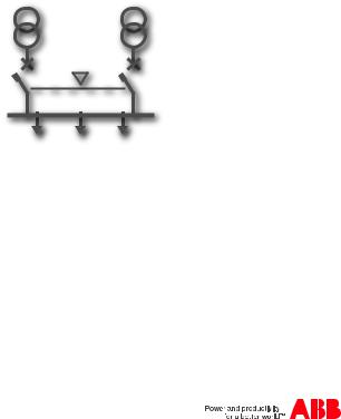
4.1 Switching Main Line – Emergency Line (2CBs)
Description
Both lines are normally present; in cause of anomaly on the main line, ATS022 switches to the emergency line used as the reserve line.
KA00428
Figure 4.1: 2CBs application layout – generator not in use
|
4. Applications of device ATS022 |
Installation and operating instructions, ATS022 |
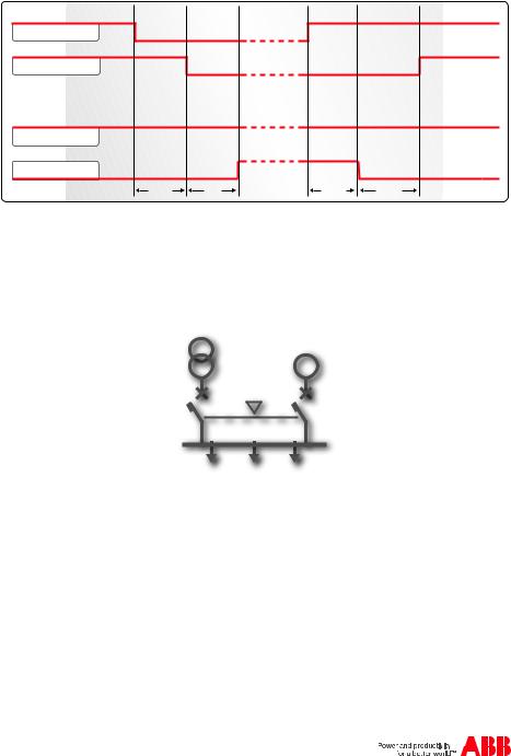
Time diagrams
Line 1 ok
CB1 CLOSED
Line 2 ok
CB2 CLOSED
Figure 4.2: 2CBs application time diagram — main line LN1
4.2 Switching Main Line – Emergency generator (2CBs)
Description
In case of main line failure ATS022 automatically starts up an emergency generator and, as soon as power on the generator side is available, ATS022 starts the automatic switching procedure.
G
KA00427
Figure 4.3: 2CBs application layout – generator in use
|
Installation and operating instructions, ATS022 |
4. |
Applications of device ATS022 |
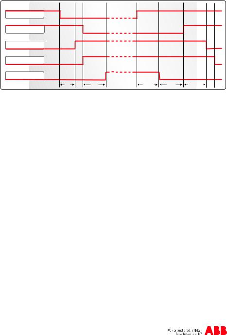
Time diagrams
Line 1 ok
CB1 CLOSED
Gen start
Line 2 ok
CB2 CLOSED
|
TS |
TCE |
TBS |
TCN |
TGOFF |
Figure 4.4: 2CBs application time diagram — generator in use
4.3 Non priority loads control (NPL)
Description
In case of main line failure the ATS022 starts the switching procedure and controls the non priority loads by opening closing circuit breaker CB3.
ATS022 acquires the CB3 open/close status from the dedicated input DI11 and commands the opening and closing by activating output DO11.
The application of non priority loads requires the use of two CT-AWE typed timed relays for operating the opening and closing of CB3.
Two configurations are possible for utilisation depending on the position of circuit breaker CB3:
•CB3 in Bus Tie position (3CBs NPL – BUS TIE)
•CB3 on starting line (3CBs NPL).
It is possible to select from two options from the menu on the display:
•only disconnection of non priority loads by opening CB3 (manual re-closure). In this case timed relays CT-AWE are not necessary
•disconnection and re-connection of non priority loads by opening and closing of CB3
For more details refer to the wiring diagrams of the product.
![]()
|
4. Applications of device ATS022 |
Installation and operating instructions, ATS022 |
CB3
NPL
Figure 4.5: Application layout 3CBs NPL BUSTIE
CB3
NPL
Figure 4.6: Application layout 3CBs NPL

|
Installation and operating instructions, ATS022 |
4. |
Applications of device ATS022 |
Time diagrams
Line 1 ok
CB1 CLOSED
Gen start
Line 2 ok
CB2 CLOSED
CB3 CLOSED
|
TS |
TCE |
TBS |
TCN |
TGOFF |
Figure 4.7: Application time diagram 3CBs NPL BUS TIE — generator in use
Line 1 ok
CB1 CLOSED
Line 2 ok
CB2 CLOSED
CB3 CLOSED
Figure 4.8: Application time diagram 3CBs NPL BUS TIE — generator not in use — main line LN1

|
4. Applications of device ATS022 |
Installation and operating instructions, ATS022 |
|||
|
Line 1 ok |
||||
|
CB1 CLOSED |
||||
|
Gen start |
||||
|
Line 2 ok |
||||
|
CB2 CLOSED |
||||
|
CB3 CLOSED |
||||
|
TS |
TCE |
TBS |
TCN |
TGOFF |
Figure 4.9: Application time diagram 3CBs NPLgenerator in use
Line 1 ok
CB1 CLOSED
Line 2 ok
CB2 CLOSED
CB3 CLOSED
Figure 4.10: Application time diagram 3CBs NPL — generator not in use — main line LN1