|
6EP4134-3AB00-0AY0
SITOP UPS1600 10A БЛОК БЕСПЕРЕБОЙНОГО ЭЛЕКТРОПИТАНИЯ ВХОД: D24 V ВЫХОД: DC DC 24 V/10A
|
| |

![]()
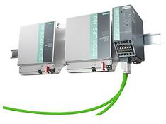
SITOP UPS1100
SITOP power supply
SITOP UPS1600 / UPS1100
Operating Instructions
SITOP UPS1600 10 A
6EP4134-3AB00-0AY0 6EP4134-3AB00-1AY0 6EP4134-3AB00-2AY0 SITOP UPS1600 20 A 6EP4136-3AB00-0AY0 6EP4136-3AB00-1AY0 6EP4136-3AB00-2AY0 SITOP UPS1100 battery module 1.2 Ah 6EP4131-0GB00-0AY0 battery module 3.2 Ah 6EP4133-0GB00-0AY0 battery module 7 Ah 6EP4134-0GB00-0AY0
05.2014
___________________
Overview
|
Safety information |
1 |
|
|
Description, device design, |
||
|
2 |
||
|
dimension drawing |
||
|
Engineering |
3 |
|
|
Mounting/removal |
4 |
|
|
Mounting position, mounting |
||
|
5 |
||
|
clearances |
||
|
Installation |
6 |
|
|
Technical data |
7 |
|
|
Safety, approvals, EMC |
8 |
|
|
Ambient conditions |
9 |
|
|
Environment |
10 |
|
|
Service & Support |
11 |
C98130-A7628-A1-4-7629

Legal information
Warning notice system
This manual contains notices you have to observe in order to ensure your personal safety, as well as to prevent damage to property. The notices referring to your personal safety are highlighted in the manual by a safety alert symbol, notices referring only to property damage have no safety alert symbol. These notices shown below are graded according to the degree of danger.
 DANGER
indicates that death or severe personal injury will result if proper precautions are not taken.
 WARNING
indicates that death or severe personal injury may result if proper precautions are not taken.
 CAUTION
indicates that minor personal injury can result if proper precautions are not taken.
NOTICE
indicates that property damage can result if proper precautions are not taken.
If more than one degree of danger is present, the warning notice representing the highest degree of danger will be used. A notice warning of injury to persons with a safety alert symbol may also include a warning relating to property damage.
Qualified Personnel
The product/system described in this documentation may be operated only by personnel qualified for the specific task in accordance with the relevant documentation, in particular its warning notices and safety instructions. Qualified personnel are those who, based on their training and experience, are capable of identifying risks and avoiding potential hazards when working with these products/systems.
Proper use of Siemens products
Note the following:
 WARNING
Siemens products may only be used for the applications described in the catalog and in the relevant technical documentation. If products and components from other manufacturers are used, these must be recommended or approved by Siemens. Proper transport, storage, installation, assembly, commissioning, operation and maintenance are required to ensure that the products operate safely and without any problems. The permissible ambient conditions must be complied with. The information in the relevant documentation must be observed.
Trademarks
All names identified by ® are registered trademarks of Siemens AG. The remaining trademarks in this publication may be trademarks whose use by third parties for their own purposes could violate the rights of the owner.
Disclaimer of Liability
We have reviewed the contents of this publication to ensure consistency with the hardware and software described. Since variance cannot be precluded entirely, we cannot guarantee full consistency. However, the information in this publication is reviewed regularly and any necessary corrections are included in subsequent editions.
|
Siemens AG |
C98130-A7628-A1-4-7629 |
Copyright © Siemens AG 2014. |
|
Industry Sector |
07/2014 Subject to change |
All rights reserved |
|
Postfach 48 48 |
||
|
90026 NÜRNBERG |
||
|
GERMANY |
Overview
Description
The DC-UPS modules augment the SITOP 24 V power supply units for uninterruptible rated currents up to 20 A from the UPS1100 battery modules based on maintenance-free lead-gel accumulators. UPS1600 with its integrated electronics detects automatically the battery type that it charges with the optimum temperature-controlled loading characteristic curve. The intelligent battery management monitors all relevant data, also for parallel-connected battery modules. The Ethernet/PROFINET interface is used to output the battery status and various current values, such as voltage, current or residual capacity. Thanks to the integrated Web server, remote diagnosis is also possible.
The slim-line UPS1600 DC-UPS module provides a dynamic overload behavior, for example, to switch on industrial PCs. The high charging current quickly restores the buffer readiness after a supply system failure. And for the deployment in stand-alone operation, the UPS can be activated from the battery for missing supply system voltage, e.g. to start the generators.
The key benefits of the product include:
●Compact SITOP UPS1600 24 V / 10 A and 20 A DC-UPS modules with digital inputs/outputs, optional with USB or two Ethernet/PROFINET interfaces
●SITOP UPS1100 24 V / 1.2 Ah, 3.2 Ah and 7 Ah battery modules with maintenance-free lead-gel accumulators and integrated electronics; intelligent battery management with automatic detection of the battery modules and selection of the optimum, temperaturecontrolled charging characteristic curve; monitoring of the operating readiness, accumulator supply cable, aging and charging state
●All diagnostic data and alarm messages are available via USB and Ethernet/PROFINET
●High dynamic overload capability: 3-fold rated current for 30 ms and 1.5-fold rated current for 5 seconds per minute
●High charging currents
●Start from battery modules for missing supply system voltage
●Remote monitoring with integrated Web server
|
SITOP UPS1600 / UPS1100 |
|
|
Operating Instructions, 05.2014, C98130-A7628-A1-4-7629 |
3 |

Overview
●SITOP UPS Manager (free software download) supports the configuration and monitoring for PC-based systems
●Complete integration in TIA: User-friendly engineering in the TIA Portal, S7 function blocks for integration in user programs and WinCC faceplates
Ordering data
The following device options are available:
SITOP UPS1600 uninterruptible power supply
|
Type |
Order number |
|
|
Input 24 VDC |
6EP4134-3AB00-0AY0 |
|
|
Output 24 VDC / 10 A |
||
|
Input 24 VDC |
6EP4134-3AB00-1AY0 |
|
|
Output 24 VDC / 10 A |
||
|
With USB interface |
||
|
Input 24 VDC |
6EP4134-3AB00-2AY0 |
|
|
Output 24 VDC / 10 A |
||
|
With PROFINET (PN) interface |
||
|
Input 24 VDC |
6EP4136-3AB00-0AY0 |
|
|
Output 24 VDC / 20 A |
||
|
Input 24 VDC |
6EP4136-3AB00-1AY0 |
|
|
Output 24 VDC / 20 A |
||
|
With USB interface |
||
|
Input 24 VDC |
6EP4136-3AB00-2AY0 |
|
|
Output 24 VDC / 20 A |
||
|
With PROFINET (PN) interface |
||
|
SITOP UPS1100 battery module |
||
|
Item |
Order number |
|
|
Battery module 1.2 Ah |
6EP4131-0GB00-0AY0 |
|
|
Battery module 3.2 Ah |
6EP4133-0GB00-0AY0 |
|
|
Battery module 7 Ah |
6EP4134-0GB00-0AY0 |
|
|
Accessories |
||
|
Type |
Order number |
|
|
Device identification labels 20 mm × 7 mm, pastel turquoise |
3RT1900-1SB20 |
|
SITOP UPS1600 / UPS1100 |
|
|
4 |
Operating Instructions, 05.2014, C98130-A7628-A1-4-7629 |
Table of contents
|
Overview |
………………………………………………………………………………………………………………………………. |
3 |
|
|
1 |
Safety information ………………………………………………………………………………………………………………….. |
9 |
|
|
2 |
Description, …………………………………………………………………………..device design, dimension drawing |
11 |
|
|
2.1 ………………………………………………………………………………………………………… |
Device description |
11 |
|
|
2.1.1 …………………………………………………………………………………………………………………….. |
UPS1600 |
11 |
|
|
2.1.2 …………………………………………………………………………………………………………………….. |
UPS1100 |
14 |
|
|
2.2 …………………………………………………………………………….. |
Connections and terminal designation |
15 |
|
|
2.2.1 …………………………………………………………………………………………………………………….. |
UPS1600 |
15 |
|
|
2.2.1.1 …………………………………………………………………………………………………………… |
Power terminals |
15 |
|
|
2.2.1.2 …………………………………………………………………………………………………………….. |
Signal terminal |
16 |
|
|
2.2.1.3 ……………………………………………………………………………………………………………………… |
USB port |
17 |
|
|
2.2.1.4 …………………………………………………………………………………….. |
PROFINET/Ethernet connection |
18 |
|
|
2.2.2 …………………………………………………………………………………………………………………….. |
UPS1100 |
19 |
|
|
2.2.2.1 …………………………………………………………………………………………………………… |
Power terminals |
19 |
|
|
2.3 ……………………………………………………………………………………………………. |
Switches and buttons |
20 |
|
|
2.3.1 …………………………………………………………………………………………………………………….. |
UPS1600 |
20 |
|
|
2.3.1.1 …………………………………………………………………………Rotary coding switch, switch-in threshold |
20 |
||
|
2.3.1.2 ………………………………………………………………………………….Rotary coding switch, backup time |
21 |
||
|
2.3.1.3 ……………………………………………………………………………………………………………. |
Jumper variants |
22 |
|
|
2.3.2 …………………………………………………………………………………………………………………….. |
UPS1100 |
25 |
|
|
2.3.2.1 ……………………………………………………………………………………… |
Buttons for battery replacement |
25 |
|
|
2.4 ……………………………………………………………………………………. |
Operating displays and signaling |
26 |
|
|
2.4.1 …………………………………………………………………………………………………………………….. |
UPS1600 |
26 |
|
|
2.4.1.1 ………………………………………………………………………………………………………………………….. |
LEDs |
26 |
|
|
2.4.1.2 ………………………………………………………………………………………………………………. |
Relay outputs |
29 |
|
|
2.4.2 …………………………………………………………………………………………………………………….. |
UPS1100 |
30 |
|
|
2.4.2.1 ………………………………………………………………………………………………………………………….. |
LEDs |
30 |
|
|
2.5 ……………………………………………………………………………………………………………… |
Block diagram |
31 |
|
|
2.5.1 …………………………………………………………………………………………………………………….. |
UPS1600 |
31 |
|
|
2.5.2 …………………………………………………………………………………………………………………….. |
UPS1100 |
32 |
|
|
2.6 …………………………………………………………………………………………………. |
Dimensions and weight |
33 |
|
|
2.6.1 …………………………………………………………………………………………………………………….. |
UPS1600 |
33 |
|
|
2.6.2 …………………………………………………………………………………………………………………….. |
UPS1100 |
35 |
|
|
3 |
Engineering ………………………………………………………………………………………………………………………… |
37 |
|
|
3.1 ……………………………………………………………………………………………………… |
General information |
37 |
|
|
3.2 …………………………………………………………………………………………………………………….. |
Alarm list |
38 |
|
|
3.3 ……………………………………………………………………………………………….. |
STEP 7 in the TIA — Portal |
41 |
|
|
3.3.1 ……………………………………………………………………….. |
Installing the Hardware Support Package |
41 |
|
|
3.3.2 …………………………………………………………………………………. |
Integrating UPS1600 into a project |
42 |
|
|
3.3.3 ………………………………………………………………………… |
Assigning the UPS1600 battery modules |
44 |
|
|
SITOP UPS1600 / UPS1100 |
|||
|
Operating Instructions, 05.2014, C98130-A7628-A1-4-7629 |
5 |

Table of contents
|
3.3.4 |
UPS1600 and UPS1100 parameters in Step 7 in the TIA Portal |
………………………………………… 46 |
|
|
3.3.5 |
Parameterizing the UPS in STEP 7 in the TIA Portal ……………………………………………………….. |
46 |
|
|
3.3.6 |
Configuring the UPS1600 in the system …………………………………………………………………………. |
49 |
|
|
3.3.7 |
Diagnostics…………………………………………………………………………………………………………………. |
53 |
|
|
3.3.8 |
Firmware update …………………………………………………………………………………………………………. |
54 |
|
|
3.3.9 |
Restore factory settings ……………………………………………………………………………………………….. |
55 |
|
|
3.4 |
STEP 7 V5………………………………………………………………………………………………………………….. |
57 |
|
|
3.4.1 |
Installing the generic station description file (GSD) ………………………………………………………….. |
57 |
|
|
3.4.2 |
Using UPS1600 in a project………………………………………………………………………………………….. |
58 |
|
|
3.4.3 |
UPS parameters in STEP 7 V5 ……………………………………………………………………………………… |
61 |
|
|
3.4.4 |
Parameterizing the UPS in STEP 7 V5…………………………………………………………………………… |
61 |
|
|
3.4.5 |
Loading the configuration into the controller (commissioning)……………………………………………. |
65 |
|
|
3.4.6 |
Diagnostics…………………………………………………………………………………………………………………. |
67 |
|
|
3.4.7 |
Firmware update …………………………………………………………………………………………………………. |
67 |
|
|
3.4.8 |
Restore factory settings ……………………………………………………………………………………………….. |
69 |
|
|
3.5 |
SITOP UPS Manager…………………………………………………………………………………………………… |
70 |
|
|
3.5.1 |
Functions of the SITOP UPS Manager …………………………………………………………………………… |
70 |
|
|
3.5.2 |
The user interface of the SITOP UPS Manager……………………………………………………………….. |
71 |
|
|
3.5.3 |
Installation/uninstallation ………………………………………………………………………………………………. |
72 |
|
|
3.5.4 |
Connection possibilities to the UPS1600 ………………………………………………………………………… |
73 |
|
|
3.5.5 |
Establishing a connection via Ethernet …………………………………………………………………………… |
73 |
|
|
3.5.6 |
Establishing a connection via USB ………………………………………………………………………………… |
79 |
|
|
3.5.7 |
Configuration in the SITOP UPS Manager ……………………………………………………………………… |
79 |
|
|
3.5.8 |
General settings ………………………………………………………………………………………………………….. |
80 |
|
|
3.5.9 |
Configuring the UPS1600 …………………………………………………………………………………………….. |
80 |
|
|
3.5.10 Behavior of the SITOP UPS Manager ……………………………………………………………………………. |
82 |
||
|
3.5.11 |
Display and visualization………………………………………………………………………………………………. |
85 |
|
|
3.5.12 |
Firmware update …………………………………………………………………………………………………………. |
88 |
|
|
3.6 |
Web server…………………………………………………………………………………………………………………. |
90 |
|
|
3.6.1 |
Accessing the Web server ……………………………………………………………………………………………. |
90 |
|
|
3.6.2 |
The user interface of the Web server……………………………………………………………………………… |
91 |
|
|
3.6.3 |
Functions of the Web server …………………………………………………………………………………………. |
92 |
|
|
3.6.4 |
Viewing the UPS1600 (base device) data ………………………………………………………………………. |
93 |
|
|
3.6.5 |
Viewing the energy storage data …………………………………………………………………………………… |
93 |
|
|
3.6.6 |
Alarm monitoring …………………………………………………………………………………………………………. |
94 |
|
|
3.6.7 |
Configuring the communications interface………………………………………………………………………. |
95 |
|
|
4 |
Mounting/removal ………………………………………………………………………………………………………………… |
97 |
|
|
4.1 |
UPS1600……………………………………………………………………………………………………………………. |
97 |
|
|
4.1.1 |
Signal connector …………………………………………………………………………………………………………. |
98 |
|
|
4.1.2 |
USB connector ……………………………………………………………………………………………………………. |
98 |
|
|
4.1.3 |
PROFINET/Ethernet connector …………………………………………………………………………………….. |
99 |
|
|
4.2 |
UPS1100………………………………………………………………………………………………………………….. |
100 |
|
|
5 |
Mounting position, mounting clearances………………………………………………………………………………….. |
103 |
|
|
5.1 |
UPS1600………………………………………………………………………………………………………………….. |
103 |
|
|
5.1.1 |
Standard mounting position ………………………………………………………………………………………… |
103 |
|
|
5.1.2 |
Other mounting positions ……………………………………………………………………………………………. |
104 |
|
|
5.2 |
UPS1100………………………………………………………………………………………………………………….. |
105 |
|
|
5.2.1 |
Standard mounting position ………………………………………………………………………………………… |
105 |
|
|
SITOP UPS1600 / UPS1100 |
|||
|
6 |
Operating Instructions, 05.2014, C98130-A7628-A1-4-7629 |

Table of contents
|
5.2.2 |
Other mounting positions …………………………………………………………………………………………….. |
105 |
|
|
5.3 |
Altitude derating …………………………………………………………………………………………………………. |
106 |
|
|
6 |
Installation ………………………………………………………………………………………………………………………… |
107 |
|
|
6.1 |
UPS1600 input side connection……………………………………………………………………………………. |
108 |
|
|
6.2 |
UPS1600 output side connection………………………………………………………………………………….. |
108 |
|
|
6.3 |
Connecting the BAT UPS1600 …………………………………………………………………………………….. |
109 |
|
|
6.4 |
USB interface …………………………………………………………………………………………………………….. |
109 |
|
|
6.5 |
PROFINET/Ethernet connection…………………………………………………………………………………… |
109 |
|
|
6.6 |
UPS1100 connections ………………………………………………………………………………………………… |
110 |
|
|
6.7 |
Maintenance………………………………………………………………………………………………………………. |
111 |
|
|
6.7.1 |
Battery………………………………………………………………………………………………………………………. |
111 |
|
|
6.7.2 |
Battery replacement……………………………………………………………………………………………………. |
112 |
|
|
7 |
Technical data …………………………………………………………………………………………………………………… |
113 |
|
|
7.1 |
Input …………………………………………………………………………………………………………………………. |
113 |
|
|
7.1.1 |
UPS1600…………………………………………………………………………………………………………………… |
113 |
|
|
7.1.2 |
UPS1100…………………………………………………………………………………………………………………… |
113 |
|
|
7.2 |
Output ………………………………………………………………………………………………………………………. |
114 |
|
|
7.2.1 |
UPS1600…………………………………………………………………………………………………………………… |
114 |
|
|
7.2.2 |
UPS1100…………………………………………………………………………………………………………………… |
114 |
|
|
7.3 |
Backup times……………………………………………………………………………………………………………… |
115 |
|
|
7.4 |
Efficiency…………………………………………………………………………………………………………………… |
115 |
|
|
7.5 |
Protection and monitoring ……………………………………………………………………………………………. |
116 |
|
|
7.6 |
MTBF ……………………………………………………………………………………………………………………….. |
116 |
|
|
7.7 |
Mechanical system …………………………………………………………………………………………………….. |
117 |
|
|
7.8 |
Dimension drawing …………………………………………………………………………………………………….. |
118 |
|
|
8 |
Safety, approvals, EMC……………………………………………………………………………………………………….. |
119 |
|
|
8.1 |
Safety ……………………………………………………………………………………………………………………….. |
119 |
|
|
8.2 |
Test voltage……………………………………………………………………………………………………………….. |
120 |
|
|
8.3 |
Approvals ………………………………………………………………………………………………………………….. |
121 |
|
|
8.4 |
EMC …………………………………………………………………………………………………………………………. |
121 |
|
|
9 |
Ambient conditions……………………………………………………………………………………………………………… |
123 |
|
|
10 |
Environment………………………………………………………………………………………………………………………. |
125 |
|
|
11 |
Service & Support ………………………………………………………………………………………………………………. |
127 |
|
SITOP UPS1600 / UPS1100 |
|
|
Operating Instructions, 05.2014, C98130-A7628-A1-4-7629 |
7 |

Table of contents
|
SITOP UPS1600 / UPS1100 |
|
|
8 |
Operating Instructions, 05.2014, C98130-A7628-A1-4-7629 |

Safety information |
1 |
 WARNING
Correct handling of the devices
When operating electrical devices, it is inevitable that certain components will carry dangerous voltages.
Therefore, failure to handle the units properly can result in death or serious physical injury as well as extensive property damage.
Only appropriately qualified personnel may work on or in the vicinity of this equipment.
Perfect, safe, and reliable operation of this equipment is dependent on proper transportation, storage, installation and mounting.
Before installation or maintenance work can begin, the system’s main switch must be switched off and measures taken to prevent it being switched on again.
If this instruction is not observed, touching live parts can result in death or serious injury.
The relevant DIN/VDE regulations or country-specific specifications (e.g. VDE 0510 Part 2 / EN50272-2) must be observed for the storage, assembly and operation of the lead accumulators. It must be ensured that the battery location is suitably ventilated. Potential ignition sources must be separated by at least 50 cm.
|
SITOP UPS1600 / UPS1100 |
|
|
Operating Instructions, 05.2014, C98130-A7628-A1-4-7629 |
9 |

Safety information
|
SITOP UPS1600 / UPS1100 |
|
|
10 |
Operating Instructions, 05.2014, C98130-A7628-A1-4-7629 |
Description, device design, dimension drawing |
2 |
2.1Device description
2.1.1UPS1600
The UPS1600 10 A and 20 A are built-in devices of the SITOP series for installation on DIN EN 50022-35×15/7.5 standard mounting rails. The relevant DIN/VDE regulations or countryspecific specifications (e.g. VDE 0510 Part 2 / EN 50272-2) must be observed for the installation of the UPS1600 devices and the UPS1100 battery modules.
See Section Installation (Page 107)
In combination with the SITOP UPS1100 battery modules, it is used to buffer the load current from the 24 V load power supplies of the SITOP series.
With their high dynamic overload capability up to the 3-fold rated current over 30 ms or up to the 1.5-fold rated current over 5 seconds per minute, they are suitable for applications with programmable logic controllers (PLCs) and industrial PCs, because they permit high switchon currents even in buffer operation.
The input of the UPS1600 DC-UPS module must be connected with the output of the supplying 24 VDC power unit. The UPS1100 battery module is connected to the Bat terminals. The loads to be buffered are supplied via the output of the UPS1600 DC-UPS module with the voltage connected at the input.
The so-called Energy Storage Link, an additional two-wire connection between the SITOP UPS1600 base device and the coded SITOP UPS1100 battery modules, is new. Furthermore, the base device detects and manages as many as six battery modules and selects the optimum, temperature-controlled charging characteristic curve. The latter provides the basis for a long service life of the battery modules. Energy Storage Link also monitors the operational readiness as well as the supply cables (wire breakage), aging (service life) and the charging state (voltage, current, residual capacity) of the accumulators. The connection to the UPS1100 battery modules is checked every 20 seconds (for voltage and incorrect polarity protection). A test with a defined loading of the lead accumulators is also performed automatically every four hours.
Battery modules of other type series and manufacturers can also be deployed, although with limited diagnostic functions, such as the display of the charging current or the end-of-charge voltage and without the possibility of temperature-controlled charging.
In the event of failure of the 24 VDC supply voltage or voltage dip below the set switch-in threshold, the loads are supplied from the battery module that is kept full charged in parallel, ready for operation. The buffering is performed in accordance with the backup time set using the rotary coding switch or until the maximum backup time (shutdown after reaching the exhaustive discharge threshold).
There are two possibilities:
a.) Power restoration only after expiration of the backup time: On absence of the input voltage at the DC-UPS module, the battery immediately assumes the supply so that the Ua output voltage remains absolutely interruption-free until the end of the backup time.
|
SITOP UPS1600 / UPS1100 |
|
|
Operating Instructions, 05.2014, C98130-A7628-A1-4-7629 |
11 |

Description, device design, dimension drawing
2.1 Device description
b.) Power restoration before expiration of the backup time: On absence of the input voltage at the DC-UPS module, the battery immediately assumes the supply so that the Ua output voltage remains absolutely interruption-free. If the «Interruption of the output voltage» setting is selected (see Chapter Jumper variants (Page 22)), the Ua output voltage is interrupted automatically for the parameterized time (default value 5 seconds) on supply system restoration during the parameterized backup time. The accumulator is already disconnected because the input voltage has already returned. If «Ua output interruption» is set, no interruption occurs because the input voltage has returned before expiration of the set backup time.
Rotary switches can be used to set the battery module switch-in threshold and the backup time. The charging current for the battery modules is set automatically and can be changed using the interface (only for types -1AY0 and -2AY0).
Eight LEDs, two potential-free changeover contacts and one NO contact indicate the UPS1600 status.
The USB interface (only -1AY0) or PROFINET/Ethernet interface (only -2AY0) handles the communication to the PC/controllers.
For details, see Sections Connections and terminal designation (Page 15) and Switches and buttons (Page 20).
Operating data and diagnostic data can be transferred using two integrated Industrial Ethernet/PROFINET ports and visualized or further processed externally as an alternative to the proven USB connection. An integrated Web server allows authorized users to export relevant data remotely via a Web browser without requiring any additional software to be installed on the remote system. The Web server is activated in the delivered state.
The free SITOP UPS Manager software tool available for Windows XP and Windows 7 systems (32and 64-bit) provides full access. This allows the overall DC-UPS installation to be configured and monitored easily using a PC. The software tool provides many possibilities for the visualization of operating and diagnostic information, such as in the form of alarm lists or easily understandable trend diagrams that, for example, provide a view of the chronological change of the charging voltage or load current of the DC-UPS.
The UPS Manager also detects when older SITOP DC-UPS modules (6EP1931-2xxxx) are deployed and displays them correctly.
The SITOP UPS1600 is fully integrated in Totally Integrated Automation (TIA), the Siemens open system architecture for integrated automation solutions. The engineering is performed in the TIA Portal and reduces to just a few clicks for the user. The UPS modules can be selected directly in the hardware catalog and in the graphical network representation accepted.
For applications without network connection, the SITOP UPS1600 is available in the variants with USB interface or digital inputs/outputs.
For stand-alone deployment, the DC-UPS can be activated without input voltage from the battery, for example, to start a generator via a directly supplied controller. (see Section Jumper variants (Page 22))
|
SITOP UPS1600 / UPS1100 |
|
|
12 |
Operating Instructions, 05.2014, C98130-A7628-A1-4-7629 |
Description, device design, dimension drawing
2.1 Device description
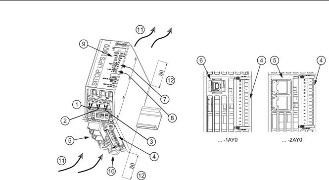
DC input DC output Bat
Signal connector
PROFINET (Ethernet) interface (only for … — 2AY0) USB interface (only for … — 1AY0)
Rotary coding switch, switch-in threshold Rotary coding switch, backup time Signaling (LEDs)
DIN rail slider Convection
Clearance above/below
Figure 2-1 UPS1600 design (example 6EP4136-3AB00-2AY0)
|
SITOP UPS1600 / UPS1100 |
|
|
Operating Instructions, 05.2014, C98130-A7628-A1-4-7629 |
13 |
Description, device design, dimension drawing
2.2 Connections and terminal designation
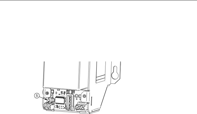
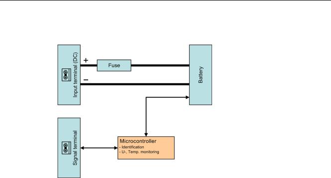
2.1.2UPS1100
The UPS1100 battery modules consist of a battery holder with two maintenance-free, closed lead-gel accumulators with terminals for the connection cables to the SITOP UPS1600 uninterruptible power supply. The UPS1100 contains a printed-circuit board for monitoring the battery functions and the communication with the UPS1600. A green LED lights continually to indicate that there is a communication connection to the UPS1600 or flashes during the accumulator replacement.
As many as six UPS1100 of the same type can be connected in parallel with a UPS1600. For an accumulator replacement, see Section Battery replacement (Page 112).
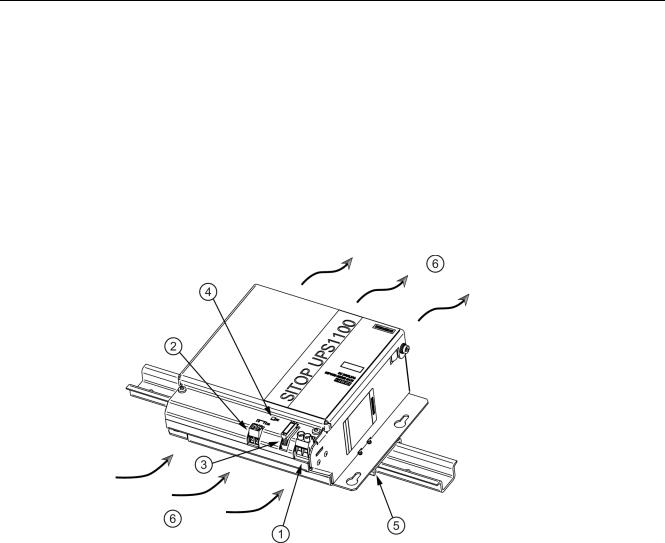
DC input X1 Signal terminal X2
Fuses F1/F2 (F2 only for 7 Ah) Signaling (LED)
Top-hat mounting rail holder (not for the 7 Ah variant) Natural convection
Figure 2-2 UPS1100 design (example 6EP4133-0GB00-0AY0)
|
SITOP UPS1600 / UPS1100 |
|
|
14 |
Operating Instructions, 05.2014, C98130-A7628-A1-4-7629 |
Description, device design, dimension drawing
2.2 Connections and terminal designation
2.2Connections and terminal designation
2.2.1UPS1600
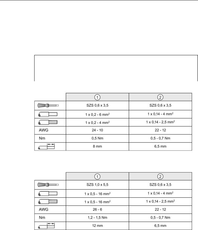
2.2.1.1Power terminals
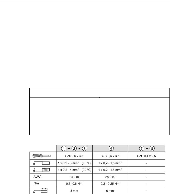
The input terminals can be used to establish the connection to the supply voltage. The output terminals are used to connect to the supplied loads.
The deployed cables must be suitable for temperatures of at least 90° C. (only for applications for UL508)
The UPS1100 battery modules are connected via BAT . (see also Section Installation (Page 107))
Connections and terminal designations (see Figure 2-1 UPS1600 design (example 6EP4136-3AB00- 2AY0) (Page 13))
|
DC input IN+, IN- |
One screw terminal each |
|
DC output OUT+, OUT- |
One screw terminal each |
|
BAT+, BAT- |
One screw terminal each |
|
Signal connector |
Connector with 14 screw terminals |
|
PROFINET (Ethernet) connection |
RJ45 plug contact |
|
USB connection |
USB-B plug contact |
Figure 2-3 UPS1600 terminal data
|
SITOP UPS1600 / UPS1100 |
|
|
Operating Instructions, 05.2014, C98130-A7628-A1-4-7629 |
15 |
Description, device design, dimension drawing
2.2 Connections and terminal designation
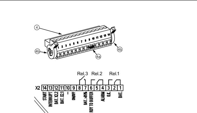
2.2.1.2Signal terminal
Figure 2-4 Signal connector
|
Figure 2-5 |
Signal connector connection schematic |
||
|
Pin |
Function |
||
|
1 |
24 VDC OK / Bat |
||
|
2 |
REL1 (changeover contact): |
||
|
Energized state: Normal operation |
|||
|
3 |
|||
|
Quiescent state: Buffer mode or off |
|||
|
4 |
Ready for buffer operation / alarm |
||
|
5 |
REL2 (changeover contact): |
||
|
Energized state: Buffer mode is possible |
|||
|
6 |
|||
|
Quiescent state: Not ready for buffering |
|||
|
Cycle 0.25 Hz: Defective battery |
|||
|
7 |
Accumulator > 85% |
||
|
8 |
REL3 (NO contact): |
||
|
Energized state: Buffering of the selected buffer time is possible, or charge state >85% |
|||
|
9 |
On/Off |
||
|
10 |
Weight |
||
|
11 |
Accumulator communication |
||
|
12 |
Accumulator supply |
||
|
13 |
Interrupt (reset after buffer mode) |
||
|
14 |
Start from the battery |
Relay contact: Maximum contact loading 30 VDC / 1 A or 125 VAC / 0.5 A
The jumper (4a) (see Figure 2-4 Signal connector (Page 16)) between pin 9 and 10 is necessary to operate the device in buffer mode.
Delivery state: Jumper between pin 9 and 10
|
SITOP UPS1600 / UPS1100 |
|
|
16 |
Operating Instructions, 05.2014, C98130-A7628-A1-4-7629 |
Description, device design, dimension drawing
2.2 Connections and terminal designation
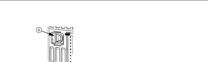
2.2.1.3USB port
Figure 2-6 USB port
The USB interface (type B) conforms fully to the USB 2.0 standard (12 MBd). Strain relief (see Section USB connector (Page 98)) is implemented using a defined cable/connector (Y-Con USB — Yamaichi company).
|
SITOP UPS1600 / UPS1100 |
|
|
Operating Instructions, 05.2014, C98130-A7628-A1-4-7629 |
17 |
Description, device design, dimension drawing
2.2 Connections and terminal designation
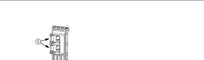
2.2.1.4PROFINET/Ethernet connection
Figure 2-7 PROFINET/Ethernet connection
Ethernet interface corresponds to the standard full duplex with up to 100 Mbit/s electrical (100BASE-TX) according to IEEE 802.3.
Properties of the Ethernet interface:
●Transmission rate 10/100 Mbit/s
●Two RJ45 sockets, i.e. integrated switch, for RJ45 connector
●Cable type 100Base-TX (CAT5)
●Auto negotiation
●Auto crossover communication via TCP/IP and PROFINET
The strain relief (see Section PROFINET/Ethernet connector (Page 99)) is implemented using a Siemens IE FastConnect RJ45.
The physics of the Ethernet interface is implemented so that PROFINET IO is possible in accordance with the standards IEC 61158 and IEC 61784-2. For PROFINET, conformance class B must be maintained as a minimum.
The Ethernet/PROFINET interface permits:
●Configuration and monitoring using the SITOP UPS Manager
●Monitoring via the Web server
●Integration and communication of the DC-UPS with other automation components from Siemens and the open environment, e.g. IPC, PLC, HMI
●Firmware update of the device via UPS Manager or STEP 7
|
SITOP UPS1600 / UPS1100 |
|
|
18 |
Operating Instructions, 05.2014, C98130-A7628-A1-4-7629 |
Description, device design, dimension drawing
2.2 Connections and terminal designation
2.2.2UPS1100
2.2.2.1Power terminals
The input terminals and the signal terminal can be used to establish the connection to the UPS1600 (see also Section Installation (Page 107))
Connections and terminal designations (see Figure 2-2 UPS1100 design (example 6EP4133-0GB00- 0AY0) (Page 14))
|
DC input +, — |
One screw terminal each |
|
Signal terminal 1, 2 |
One screw terminal each |
Figure 2-8 Terminal data for 6EP4131-0GB00-0AY0 and 6EP4133-0GB00-0AY0
Figure 2-9 Terminal data for 6EP4134-0GB00-0AY0
|
SITOP UPS1600 / UPS1100 |
|
|
Operating Instructions, 05.2014, C98130-A7628-A1-4-7629 |
19 |

Description, device design, dimension drawing
2.3 Switches and buttons
2.3Switches and buttons
2.3.1UPS1600
2.3.1.1Rotary coding switch, switch-in threshold
The switch-in threshold can be set using the rotary coding switch on the device front between 21.0 V and 25-0 V (21 — 21.5 — 22 — 22.5 — 23 — 24 — 25 volt). The delivery state is 22.5 V
For devices with an interface (…-1AY0, …-2AY0), the coding switch has an additional position (REN, see the following figure). If this is selected, the software settings (for the switch-in threshold and the backup time) apply rather than the hardware settings. In the switch position REN, the connection X2.13 (INTERRUPT — reset after buffer operation) of the signal terminal (see Section Signal terminal (Page 16)) has no effect.
Figure 2-10 Rotary coding switch, switch-in threshold
Note
It is only permissible to actuate the rotary coding switch using an insulated screwdriver.
For notes on actuating the rotary coding switch (screwdriver, torque), see Figure 2-3
UPS1600 terminal data (Page 15).
|
SITOP UPS1600 / UPS1100 |
|
|
20 |
Operating Instructions, 05.2014, C98130-A7628-A1-4-7629 |
![]()
Description, device design, dimension drawing
2.3 Switches and buttons
2.3.1.2Rotary coding switch, backup time
The backup time is set using the rotary coding switch on the device front between 30 seconds and MAX (32767 seconds) in the steps 0.5 minute (30 seconds), 1 minute,
2 minutes, 5 minutes, 10 minutes, 20 minutes and MAX (32767 seconds). Delivery state is MAX
The coding switch has an additional setting OFF (see following figure). If this is selected and the additional threshold rotary coding switch is not set to REN, the buffering is disabled.
If the backup time is also set using the software (only for devices with an interface (…-1AY0, …-2AY0)) (possible setting range, see Section Parameterizing the UPS in STEP 7 V5 (Page 61)), the rotary coding switch for the switch-in threshold (see Section Rotary coding switch, switch-in threshold (Page 20)) must be set to REN.
Figure 2-11 Rotary coding switch, backup time
Note
It is only permissible to actuate the rotary coding switch using an insulated screwdriver.
For notes on actuating the rotary coding switch (screwdriver, torque), see Figure 2-3
UPS1600 terminal data (Page 15).
|
SITOP UPS1600 / UPS1100 |
|
|
Operating Instructions, 05.2014, C98130-A7628-A1-4-7629 |
21 |

Description, device design, dimension drawing
2.3 Switches and buttons
2.3.1.3Jumper variants
On/Off (pin 9)
The wire jumper on the signal connector between pin 9 and pin 10 (see Figure 2-4 Signal connector (Page 16)) is used to enable/disable the buffer mode.
Buffer mode is only possible if the wire jumper ON/OFF is closed, or for UPS1600 devices with interface, also if the rotary coding switch connection threshold is at the «REN» position. From firmware release V1.20, the wire jumper ON/OFF has priority over the position of the connection threshold rotary coding switch.
As a consequence, it is possible to enable or disable buffer mode using a floating contact (e.g. a contact in the plant or system). The contact is switched instead of the ON/OFF wire jumper. (Note: For reasons relating to noise insensitivity, approximately in the range 5…10 mA, Umax = 15 VDC, SELV: Imax = 10 mA)
Note
The external circuit must meet the requirements relating to SELV circuits according to EN60950-1.
Changes are also effective in the buffer mode.
Table 2- 1 With interface (up to firmware release less than V1.20)
|
Rotary coding |
Rotary coding |
Wire jumper ON/OFF to ground |
Result |
|
switch, |
switch, |
||
|
buffer time |
connection |
||
|
threshold |
|||
|
OFF |
21 — 25 |
Yes |
Buffering not permitted |
|
0.5 — MAX |
21 — 25 |
Yes |
Buffer mode permitted |
|
(buffer time in |
|||
|
accordance with the |
|||
|
settings or infinite |
|||
|
buffer time) |
|||
|
OFF, 0.5 — MAX |
21 — 25 |
No |
Buffering not permitted |
|
OFF, 0.5 — MAX |
REN |
Not relevant |
The software settings |
|
apply |
|
SITOP UPS1600 / UPS1100 |
|
|
22 |
Operating Instructions, 05.2014, C98130-A7628-A1-4-7629 |

Description, device design, dimension drawing
2.3 Switches and buttons
Table 2- 2 With interface (from firmware release V1.20 and higher)
|
Rotary coding |
Rotary coding |
Wire jumper ON/OFF to ground |
Result |
|
switch, |
switch, |
||
|
buffer time |
connection |
||
|
threshold |
|||
|
OFF |
21 — 25 |
Yes |
Buffering not permitted |
|
0.5 — MAX |
21 — 25 |
Yes |
Buffer mode permitted |
|
(buffer time in |
|||
|
accordance with the |
|||
|
settings or infinite |
|||
|
buffer time) |
|||
|
OFF, 0.5 — MAX |
21 — 25, REN |
No |
Buffering not permitted |
|
OFF, 0.5 — MAX |
REN |
Yes |
The software settings |
|
apply |
Table 2- 3 Without interface (all firmware releases)
|
Rotary coding |
Rotary coding |
Wire jumper |
Result |
|
switch, |
switch, |
ON/OFF to ground |
|
|
buffer time |
connection |
||
|
threshold |
|||
|
OFF |
21 — 25 |
Not relevant |
Buffering not permitted |
|
0.5 — MAX |
21 — 25 |
Yes |
Buffer mode permitted (buffer time |
|
in accordance with the settings or |
|||
|
infinite buffer time) |
|||
|
0.5 — MAX |
21 — 25 |
No |
Buffering not permitted |
Delivery state: Wire jumper between pin 9 and 10
Interruption of the output voltage (pin 13)
A wire jumper on the signal connector between pin 13 and pin 10 is used to enable/disable the interruption of the output voltage for the parameterized time (default value 5 seconds) for supply system restoration during the buffer time.
To prevent data losses, the PCs must be shut down timely before the buffer time ends. If the input voltage returns after the shutdown has already started, buffer mode is ended and the UPS1600 goes into normal operation. The PC will be shut down, however, it is not switched off. PCs, which do not have an on/off switch, can only be rebooted by switching off the power and switching on again.
For customers that use their own software, this pulse must be selected at the DC UPS module.
Note
This function is possible only in conjunction with the R signal (DC UPS Manager).
|
SITOP UPS1600 / UPS1100 |
|
|
Operating Instructions, 05.2014, C98130-A7628-A1-4-7629 |
23 |

Description, device design, dimension drawing
2.3 Switches and buttons
Start from the battery (pin 14)
The start from the battery is initiated by closing the contact pin 14 to ground (pin 10). This jumper must not provide a permanent connection, but must be controlled using a button. The input is designed so that a single lamp with a permissible supply voltage of between 12 and 30 V and 8 to 15 mA can be switched in series to the switching contact. If while pressing the button, the UPS1600 enters buffer mode, the set buffer time will be started. For example, if 5 minutes is set, the UPS1600 sets itself off after 5 minutes. If the input voltage returns during the buffer time, the UPS1600 switches to normal operation.
If the input voltage is available, the DC UPS starts in the normal operation.
If the UPS1600 is switched-off remotely via the interface (also possible when input voltage is available), start from the battery can be used to restart the UPS1600.
Charge current setting (pin 10 / 11 / 12)
For uncoded batteries, the size of the charge current can be changed by placing jumpers between the terminals X2.10 (ground) and X2.11 or X2.12.
Table 2- 4 Charge current
|
UPS1600 10 A |
UPS1600 20 A |
Terminal X2.11 |
Terminal X2.12 |
|
0.3 A |
0.8 A |
open |
open |
|
0.8 A |
1.75 A |
open |
connected with X2.10 |
|
Max. |
Max. |
connected with X2.10 |
open |
|
SITOP UPS1600 / UPS1100 |
|
|
24 |
Operating Instructions, 05.2014, C98130-A7628-A1-4-7629 |
Description, device design, dimension drawing
2.3 Switches and buttons
2.3.2UPS1100
2.3.2.1Buttons for battery replacement
For the UPS1100, a button for the battery replacement is located under the cover. Battery replacement, see Section Battery replacement (Page 112)
Figure 2-12 Buttons for battery replacement
|
SITOP UPS1600 / UPS1100 |
|
|
Operating Instructions, 05.2014, C98130-A7628-A1-4-7629 |
25 |
Description, device design, dimension drawing
2.4 Operating displays and signaling
2.4Operating displays and signaling
2.4.1UPS1600
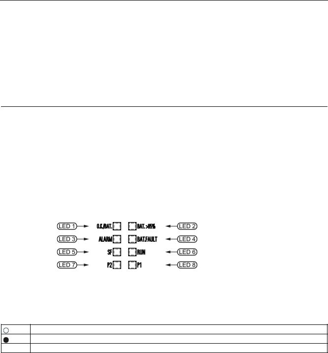
2.4.1.1LEDs
|
6EP4134-3AB00-… |
|
|
6EP4136-3AB00-… |
|
|
Status display |
LED1: DC-UPS operating mode |
|
LED2: Charge state |
|
|
LED3: Ready for buffering |
|
|
LED4: Accumulator test |
|
|
LED5: Specific diagnostic displays for PROFINET |
|
|
LED6: Specific diagnostic displays for PROFINET |
|
|
LED7: Ethernet port 1 connection state |
|
|
LED8: Ethernet port 2 connection state |
|
|
LED 7 and 8 are active only for … -2AY0 |
Figure 2-13 Operating displays
Legend:
LED off
LED lights up
 0,5/3 LED flashes on in 0.5-second and off in 3-second intervals
|
SITOP UPS1600 / UPS1100 |
|
|
26 |
Operating Instructions, 05.2014, C98130-A7628-A1-4-7629 |

Description, device design, dimension drawing
2.4 Operating displays and signaling
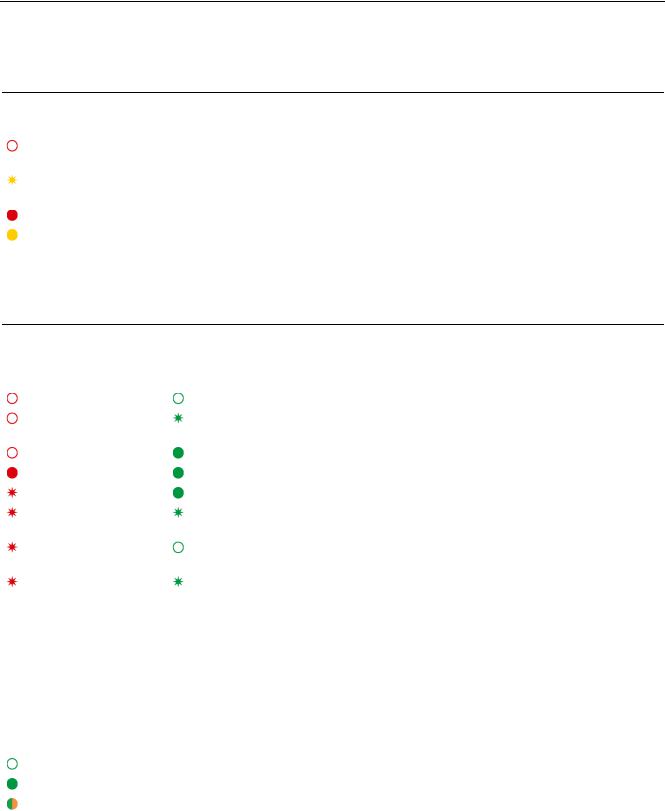
LED 1 (OK/Bat)
|
Signaling |
6EP4134-3AB00-… |
|
6EP4136-3AB00-… |
|
|
Off |
DC-UPS off |
|
Red |
DC-UPS defect (severe hardware fault) |
|
Flashing red (0.5/0.5) |
Firmware update |
|
Flashing red (1/1) |
Software corrupted |
|
Flashing yellow |
Critical temperature reached, overtemperature or overvoltage at the input |
|
(0.5/0.5) |
|
|
Flashing yellow (0.5/3) |
Buffer mode, output off |
|
Yellow |
Buffer mode |
|
Flashing green (0.5/3) |
DC-UPS OK, output off |
|
Green |
DC-UPS OK |
LED 2 (Bat. > 85%)
|
Signaling |
6EP4134-3AB00-… |
|
6EP4136-3AB00-… |
|
|
Flashing green |
Updating the firmware |
|
(0.5/0.5) |
|
|
Off |
Battery charge state < 85% |
|
Green |
Battery charge state > 85% |
|
LED 3 (alarm) |
|
|
Signaling |
6EP4134-3AB00-… |
|
6EP4136-3AB00-… |
|
|
Red |
Output off for 45 seconds because of overcurrent, overtemperature or buffer operation not |
|
possible |
|
|
Off |
Buffer operation possible |
|
SITOP UPS1600 / UPS1100 |
|
|
Operating Instructions, 05.2014, C98130-A7628-A1-4-7629 |
27 |
Description, device design, dimension drawing
2.4 Operating displays and signaling
LED 4 (accumulator / bat. fault)
|
Signaling |
6EP4134-3AB00-… |
|
6EP4136-3AB00-… |
|
|
Off |
Battery OK or uncoded battery modules connected or backup time rotary coding switch at |
|
position MAX |
|
|
Flashing yellow |
Battery outside the permitted temperature range |
|
(0.5/0.5) |
|
|
Red |
Battery defective |
|
Yellow |
Selected backup time cannot be attained |
LED 5 and LED 6 (PROFINET LEDs)
|
Signaling |
6EP4134-3AB00-2AY0 |
|
|
6EP4136-3AB00-2AY0 |
||
|
LED 5 (SF) |
LED 6 (RUN) |
|
|
Off |
Off |
No connection to a PROFINET IO controller |
|
Off |
Flashing green |
Configuration by the PROFINET IO controller |
|
(0.5/0.5) |
||
|
Off |
Green |
Application started successfully, module OK |
|
Red |
Green |
Application started successfully, module not OK |
|
Flashing red (0,1/0,1) |
Green |
Application in progress, diagnosis can be called |
|
Flashing red (0.5/0.5) |
Flashing green |
Self-test in progress (flashing alternately every 3 seconds) |
|
(0.5/0.5) |
||
|
Flashing red (0.5/0.5) |
Off |
DCP requires device identification (LED flashes for |
|
3 seconds) |
||
|
Flashing red (0.5/0.5) |
Flashing green |
Updating the firmware |
|
(0.5/0.5) |
||
|
LED 5 and 6 are active only for … -2AY0 |
||
|
LED 7 (Ethernet LED / P2) |
||
|
Signaling |
6EP4134-3AB00-2AY0 |
|
|
6EP4136-3AB00-2AY0 |
||
|
Off |
Device not connected with controller |
|
|
Green |
Device connected with controller, no activity |
|
|
Green/orange alternately |
Device connected with controller, send/receive data (RX/TX) |
LED 7 is active only for … -2AY0
|
SITOP UPS1600 / UPS1100 |
|
|
28 |
Operating Instructions, 05.2014, C98130-A7628-A1-4-7629 |
Description, device design, dimension drawing
2.4 Operating displays and signaling
LED 8 (Ethernet LED / P1)
|
Signaling |
6EP4134-3AB00-2AY0 |
|
6EP4136-3AB00-2AY0 |
|
|
Off |
Device not connected with controller |
|
Green |
Device connected with controller, no activity |
|
Green/orange alternately |
Device connected with controller, send/receive data (RX/TX) |
LED 8 is active only for … -2AY0
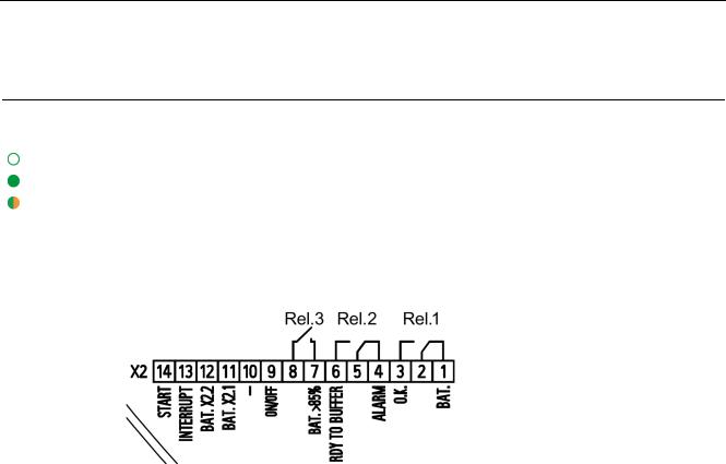
2.4.1.2Relay outputs
Figure 2-14 Signal connector connection schematic
REL1 (changeover contact): Energized state: Normal operation Quiescent state: Buffer mode or off
REL2 (changeover contact):
Energized state: Buffer operation is possible Quiescent state: Not ready for buffering
Cycle 0.25 Hz: Accumulator defective or set backup time is not attained
REL3 (NO contact):
Energized state: Buffering of the selected backup time is possible, or charge state >85%
|
SITOP UPS1600 / UPS1100 |
|
|
Operating Instructions, 05.2014, C98130-A7628-A1-4-7629 |
29 |

Description, device design, dimension drawing
2.4 Operating displays and signaling
2.4.2UPS1100
2.4.2.1LEDs
|
6EP4131-0GB00-0AY0 (1.2 Ah) |
|
|
6EP4133-0GB00-0AY0 (3.2 Ah) |
|
|
6EP4134-0GB00-0AY0 (7 Ah) |
|
|
Status display |
LED battery |
|
Figure 2-15 |
6EP4131-0GB00-0AY0 example |
|
|
Table 2- 5 |
LED battery |
|
|
Signaling |
6EP4131-0GB00-0AY0 (1.2 Ah) |
|
|
6EP4133-0GB00-0AY0 (3.2 Ah) |
||
|
6EP4134-0GB00-0AY0 (7 Ah) |
||
|
Flashing green |
Fault or alarm |
|
|
(0.5/0.5) |
||
|
Off |
Battery off, no communication |
|
|
Green |
Battery OK |
|
SITOP UPS1600 / UPS1100 |
|
|
30 |
Operating Instructions, 05.2014, C98130-A7628-A1-4-7629 |
![]()
Description, device design, dimension drawing
2.5 Block diagram
2.5Block diagram
2.5.1UPS1600
Figure 2-16 UPS1600 block diagram
|
SITOP UPS1600 / UPS1100 |
|
|
Operating Instructions, 05.2014, C98130-A7628-A1-4-7629 |
31 |
Description, device design, dimension drawing
2.6 Dimensions and weight
2.5.2UPS1100
Figure 2-17 UPS1100 block diagram
|
SITOP UPS1600 / UPS1100 |
|
|
32 |
Operating Instructions, 05.2014, C98130-A7628-A1-4-7629 |
Description, device design, dimension drawing
2.6 Dimensions and weight
2.6Dimensions and weight
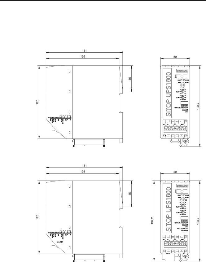
2.6.1UPS1600
Figure 2-18 6EP4134-3AB00-0AY0, 6EP4134-3AB00-1AY0, 6EP4136-3AB00-0AY0,6EP4136-
3AB00-1AY0 dimensioned drawing
Figure 2-19 6EP4134-3AB00-2AY0, 6EP4136-3AB00-2AY0 dimensioned drawing
|
SITOP UPS1600 / UPS1100 |
|
|
Operating Instructions, 05.2014, C98130-A7628-A1-4-7629 |
33 |

Description, device design, dimension drawing
2.6 Dimensions and weight
|
6EP4134-3AB00-0AY0 |
6EP4134-3AB00-1AY0 |
6EP4134-3AB00-2AY0 |
|
|
Dimensions (W × H × D) |
50 × 138.7 × 125 |
50 × 138.7 × 125 |
50 × 138.7 × 125 |
|
in mm |
|||
|
Weight |
Approx. 0.38 kg |
Approx. 0.4 kg |
Approx. 0.45 kg |
|
6EP4136-3AB00-0AY0 |
6EP4136-3AB00-1AY0 |
6EP4136-3AB00-2AY0 |
|
|
Dimensions (W × H × D) |
50 × 138.7 × 125 |
50 × 138.7 × 125 |
50 × 138.7 × 125 |
|
in mm |
|||
|
Weight |
Approx. 0.39 kg |
Approx. 0.41 kg |
Approx. 0.45 kg |
|
SITOP UPS1600 / UPS1100 |
|
|
34 |
Operating Instructions, 05.2014, C98130-A7628-A1-4-7629 |

Description, device design, dimension drawing
2.6 Dimensions and weight
2.6.2UPS1100
Figure 2-20 6EP4131-0GB00-0AY0 dimensioned drawing
Figure 2-21 6EP4133-0GB00-0AY0 dimensioned drawing
|
SITOP UPS1600 / UPS1100 |
|
|
Operating Instructions, 05.2014, C98130-A7628-A1-4-7629 |
35 |
Description, device design, dimension drawing
2.6 Dimensions and weight
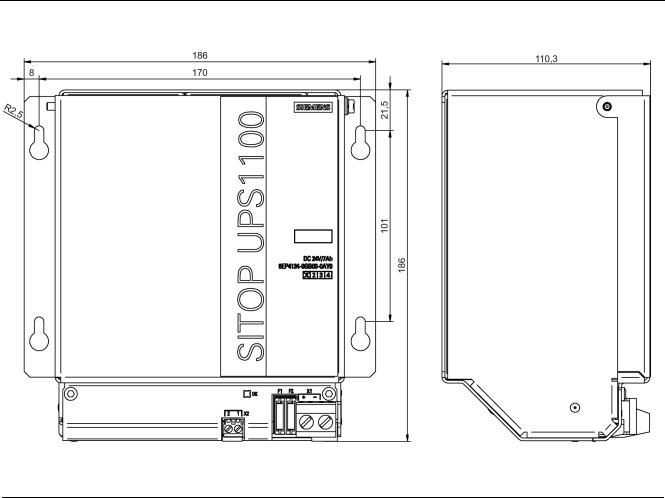
Figure 2-22 6EP4134-0GB00-0AY0 dimensioned drawing
|
6EP4131-0GB00-0AY0 |
6EP4133-0GB00-0AY0 |
6EP4134-0GB00-0AY0 |
|
|
(1.2 Ah) |
(3.2 Ah) |
(7 Ah) |
|
|
Dimensions (W × H × D) |
89 × 130 × 107 |
190 × 169 × 79 |
186 × 186 × 110 |
|
in mm |
|||
|
Weight |
Approx. 1.9 kg |
Approx. 3.8 kg |
Approx. 6.1 kg |
|
SITOP UPS1600 / UPS1100 |
|
|
36 |
Operating Instructions, 05.2014, C98130-A7628-A1-4-7629 |

3.1General information
Contents of the «Engineering» section
This section describes those software tools offered by Siemens that are compatible with SITOP UPS1600 . The software tools are introduced with their functions, the associated requirements and the operation. The software products are:
●STEP 7 in the TIA Portal from V12
●STEP 7 V5.4 or higher
●SITOP UPS Manager
●Web server
Functions of the individual software products
●STEP 7 in the TIA Portal
The UPS1600 can be used with STEP 7 in the TIA Portal from Version 12 with service pack 1 (SP1).
As the UPS1600 has been saved in the hardware catalog of STEP 7 in the TIA Portal , it can be integrated in the project, parameterized and diagnosed.
●STEP 7 V5
The UPS1600 can be used with STEP 7 V5 from Version 5.4.
As UPS1600 has been saved in the hardware catalog of STEP 7 V5 it can be integrated in the project, parameterized and diagnosed.
●SITOP UPS Manager
UPS1600 can be parameterized with SITOP UPS Manager . In addition, the protection of individual computers or computer networks can be determined by shutdown conditions after the failure of the supply voltage.
●Web server
The web server can be used to check the parameters and diagnose the UPS1600.
Note
SITOP UPS Manager and TIA cannot simultaneously access the UPS1600.
|
SITOP UPS1600 / UPS1100 |
|
|
Operating Instructions, 05.2014, C98130-A7628-A1-4-7629 |
37 |

Engineering
3.2 Alarm list
3.2Alarm list
The help text provides further information about a pending alarm.
The Extended Error Type helps to interpret the alarms in self-programmed S7 function blocks.
The maintenance specifies the severity of the alarm: MR = Maintenance Required
MD = Maintenance Demanded F = Failure
|
Error |
Extended |
Maintenance |
Alarm Text |
Help Text |
|
Type |
Error Type |
|||
|
256 |
— |
F |
Device failure |
Device failure |
|
256 |
1 |
MR |
Corrupt software |
Software is corrupt — try to update the software |
|
256 |
2 |
MR |
Wrong checksum |
Internal error: Communication disrupted |
|
256 |
3 |
MR |
Parameter corrupt |
Attempting to write to an unknown or read-only |
|
object. |
||||
|
256 |
4 |
MR |
Unknown parameter |
Attempting to set a parameter that is not known by |
|
DC UPS. |
||||
|
256 |
5 |
MR |
Wrong message length |
Internal error: Communication disrupted |
|
256 |
6 |
MR |
Wrong parameter |
Parameter value is not within the specified range |
|
256 |
7 |
MR |
Command not accepted |
An incorrect command was sent to the DC UPS |
|
256 |
8 |
MR |
Communication error: Wrong |
Syntax error in command |
|
length field |
||||
|
256 |
9 |
MR |
Wrong request |
Error in sent message: Unknown request sent. |
|
256 |
10 |
MR |
Cannot write to object |
Attempting to write a parameter that is «read-only» |
|
256 |
11 |
MR |
Object pending |
DC UPS cannot provide data for the requested |
|
object. |
||||
|
256 |
12 |
MR |
Battery not available |
Attempting to access a battery that is not available. |
|
Either the battery with the requested number was |
||||
|
never connected or communication with this battery |
||||
|
was interrupted. |
||||
|
256 |
13 |
MR |
EEPROM write error |
Saving DC UPS parameters failed. Device is |
|
defective. |
||||
|
256 |
14 |
MR |
Unknown alarm |
Internal error: Wrong parameter at execution of test |
|
command. |
||||
|
256 |
15 |
MR |
Command outside range |
An incorrect command was sent to the DC UPS |
|
256 |
16 |
MR |
SW update is currently being |
The command sent cannot be executed as long as |
|
executed |
the program is running. |
|||
|
256 |
17 |
MR |
No software update |
Cannot execute the sent command because no |
|
software update has been started. |
||||
|
256 |
18 |
MR |
Wrong battery number |
Attempting to retrieve data about a battery which |
|
does not exist or is not connected. |
||||
|
256 |
19 |
MR |
Wrong address |
Wrong Flash address in software update — software |
|
update file is corrupt. |
||||
|
256 |
20 |
MR |
Write error |
Cannot write to Flash — hardware may be defective |
|
256 |
21 |
MR |
Read error |
Unable to read EEPROM. Device is defective. |
|
SITOP UPS1600 / UPS1100 |
||||
|
38 |
Operating Instructions, 05.2014, C98130-A7628-A1-4-7629 |
|
Engineering |
|||||
|
3.2 Alarm list |
|||||
|
Error |
Extended |
Maintenance |
Alarm Text |
Help Text |
|
|
Type |
Error Type |
||||
|
256 |
22 |
MR |
Wrong device ID |
An attempt was made to update the software with |
|
|
an update file that is not suitable for the DC UPS. |
|||||
|
256 |
23 |
MR |
Corrupt data record |
Error during software update — try to update the |
|
|
software again |
|||||
|
256 |
24 |
MR |
Wrong update |
An attempt was made to update the software with |
|
|
an invalid update file. The update file is probably too |
|||||
|
old. |
|||||
|
256 |
25 |
MR |
Too much data |
An entry in the software update cannot contain more |
|
|
than 32 bytes of reference data. |
|||||
|
256 |
26 |
F |
Device failure |
Device failure |
|
|
257 |
— |
F |
Device diagnostics |
Device diagnostics |
|
|
257 |
1 |
MD |
Buffer mode is not possible |
Buffer mode is not possible — check settings, |
|
|
cabling, fuse, and battery voltages |
|||||
|
257 |
2 |
MD |
Device temperature critical |
Internal device temperature close to the upper limit. |
|
|
(too high) |
Caution: The highest permitted temperature could |
||||
|
be exceeded! |
|||||
|
257 |
3 |
MD |
Device temperature critical |
Internal device temperature close to the lower limit. |
|
|
(too low) |
Device could leave the operating range. |
||||
|
257 |
4 |
F |
High-resistance connection |
High-resistance connection to battery — check |
|
|
to battery |
battery power cable |
||||
|
257 |
5 |
F |
Connection to battery |
Connection to battery interrupted — check connection |
|
|
interrupted |
and fuse |
||||
|
257 |
6 |
MD |
Unknown battery |
Data from the battery cannot be read correctly. |
|
|
Battery is defective or not supported by SIEMENS. |
|||||
|
257 |
7 |
MR |
Overcurrent |
Output current of DC UPS is too high. Output will be |
|
|
switched off for 20s. The output will be switched on |
|||||
|
again after 20s. |
|||||
|
257 |
8 |
MR |
Reset buffer timer |
The PC shuts down |
|
|
257 |
9 |
MR |
DC UPS switched off |
DC UPS switched off — buffer time exceeded or the |
|
|
PC has been shut down |
|||||
|
257 |
10 |
MR |
Output switched off |
The DC UPS output was shut down as result of |
|
|
executing an instruction or an error situation (e.g. |
|||||
|
overtemperature, excessive output current). |
|||||
|
257 |
11 |
MR |
Output switched on |
The DC UPS output was switched on again as |
|
|
result of executing an instruction or the correction of |
|||||
|
an error situation. |
|||||
|
257 |
12 |
MR |
Reset performed |
Input voltage to DC UPS was OK again before the |
|
|
buffer time expired. Connected devices are reset by |
|||||
|
switching off the DC UPS outputs for the configured |
|||||
|
time. |
|||||
|
257 |
13 |
MR |
Reserve |
||
|
257 |
14 |
MR |
Software update successful |
Previous software update was successful — DC UPS |
|
|
is operational again. |
|||||
|
257 |
15 |
MR |
Input voltage is too high |
Input voltage exceeds 30 V. DC UPS is not |
|
|
operational. |
|||||
|
257 |
16 |
MD |
Surplus battery |
More than 6 batteries connected |
|
|
SITOP UPS1600 / UPS1100 |
|||||
|
Operating Instructions, 05.2014, C98130-A7628-A1-4-7629 |
39 |
 Loading…

Посмотреть инструкция для Siemens SITOP UPS1600 бесплатно. Руководство относится к категории источники бесперебойного питания, 1 человек(а) дали ему среднюю оценку 7.4. Руководство доступно на следующих языках: английский. У вас есть вопрос о Siemens SITOP UPS1600 или вам нужна помощь? Задайте свой вопрос здесь
Siemens SITOP UPS1600 является надежным и эффективным источником бесперебойного питания для промышленных приложений. Этот устройство используется для поддержания непрерывной работы электронных систем, когда возникают кратковременное падение электропитания или сбои в сети. UPS1600 имеет высокую мощность и быстро переключается на резервный источник питания в случае отключения электроснабжения.
Продукт оснащен передовыми технологиями защиты от перегрузок и импульсов, а также имеет возможность удаленного мониторинга и управления. UPS1600 обеспечивает надежное питание в течение длительного времени, что делает его идеальным для использования в критически важных системах.
Дополнительно, Siemens SITOP UPS1600 имеет компактный дизайн и прост в использовании. Устройство имеет широкий диапазон рабочих температур, что позволяет использовать его в различных условиях и средах.
В целом, Siemens SITOP UPS1600 — это надежный и высокоэффективный источник бесперебойного питания, который подходит для широкого спектра промышленных применений.
Не можете найти ответ на свой вопрос в руководстве? Вы можете найти ответ на свой вопрос ниже, в разделе часто задаваемых вопросов о Siemens SITOP UPS1600.
Инструкция Siemens SITOP UPS1600 доступно в русский?
К сожалению, у нас нет руководства для Siemens SITOP UPS1600, доступного в русский. Это руководство доступно в английский.
Не нашли свой вопрос? Задайте свой вопрос здесь
-
Contents
-
Table of Contents
-
Troubleshooting
-
Bookmarks
Quick Links
SITOP power supplies
SITOP UPS1600 / UPS1100
Manual
SITOP UPS1600 10 A
6EP4134-3AB00-0AY0
6EP4134-3AB00-1AY0
6EP4134-3AB00-2AY0
SITOP UPS1600 20 A
6EP4136-3AB00-0AY0
6EP4136-3AB00-1AY0
6EP4136-3AB00-2AY0
SITOP UPS1600 40 A
6EP4137-3AB00-0AY0
6EP4137-3AB00-1AY0
6EP4137-3AB00-2AY0
SITOP UPS1100
Battery module 1.2 Ah
6EP4131-0GB00-0AY0
Battery module 2.5 Ah
6EP4132-0GB00-0AY0
Battery module 3.2 Ah
6EP4133-0GB00-0AY0
Battery module 5 Ah
6EP4133-0JB00-0AY0
Battery module 7 Ah
6EP4134-0GB00-0AY0
Battery module 12 Ah
6EP4135-0GB00-0AY0
04.2017
A5E37775406-8-76
Overview
Safety instructions
Description, device design,
dimension drawing
Engineering and remote
access
Troubleshooting
Mounting/removing
Mounting position, mounting
clearances
Installation
Technical data
Safety, approvals, EMC
Environmental conditions
Environment
Service & Support
1
2
3
4
5
6
7
8
9
10
11
12